
Antenna apparatus, printed wiring board, printed circuit board, communication adapter and portable electronic equipment

a technology of printed wiring boards and antennas, applied in the direction of resonant antennas, antenna earthings, elongated active elements, etc., can solve the problems of hardly applicable to wristwatch-size portable electronic equipment or the like, requiring to be made smaller, and poor layout freedom

Active Publication Date: 2005-09-20
SEIKO EPSON CORP
View PDF15 Cites 88 Cited by
  • Summary
  • Abstract
  • Description
  • Claims
  • Application Information

AI Technical Summary

Benefits of technology

[0012]Accordingly, an object of the present invention is to provide an antenna apparatus, a printed wiring board, a printed circuit board, a communication adapter and portable electronic equipment that make it possible to improve the mounting density of an entire circuit and to achieve a smaller printed wiring board while securing the characteristics (sensitivity, in particular) of an antenna.
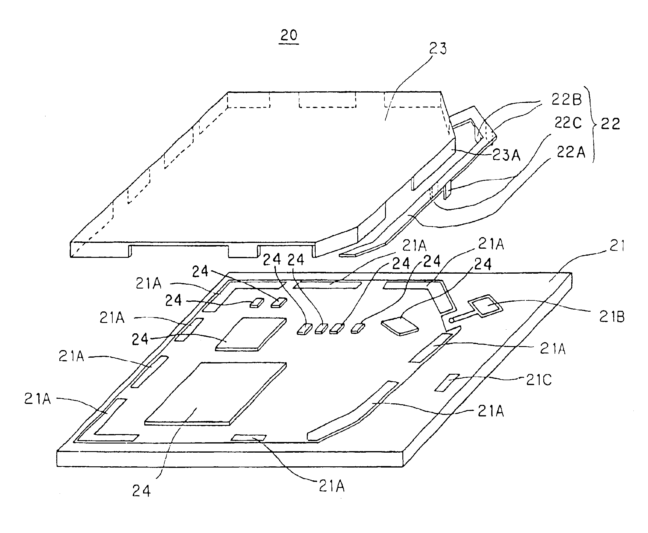
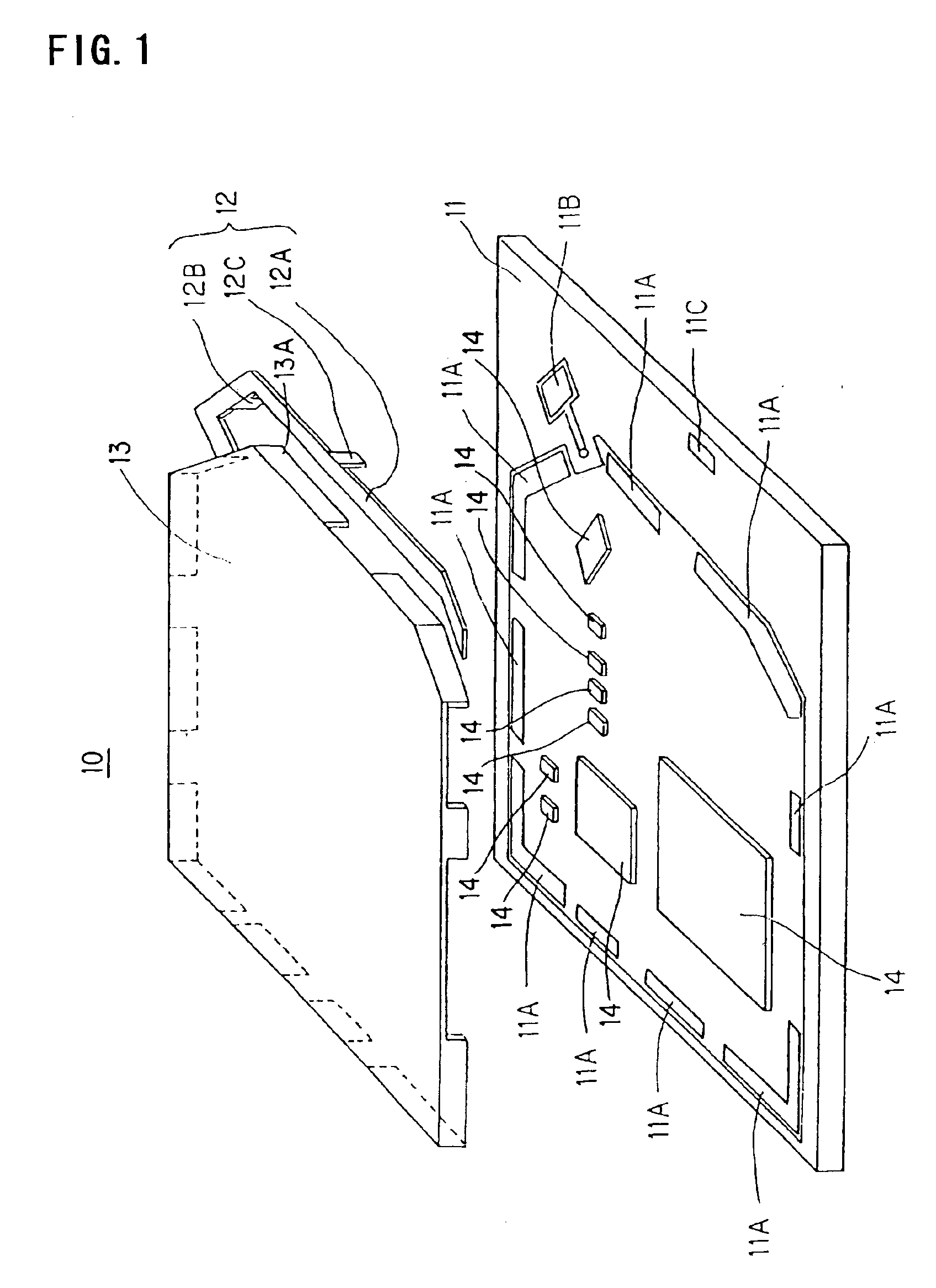
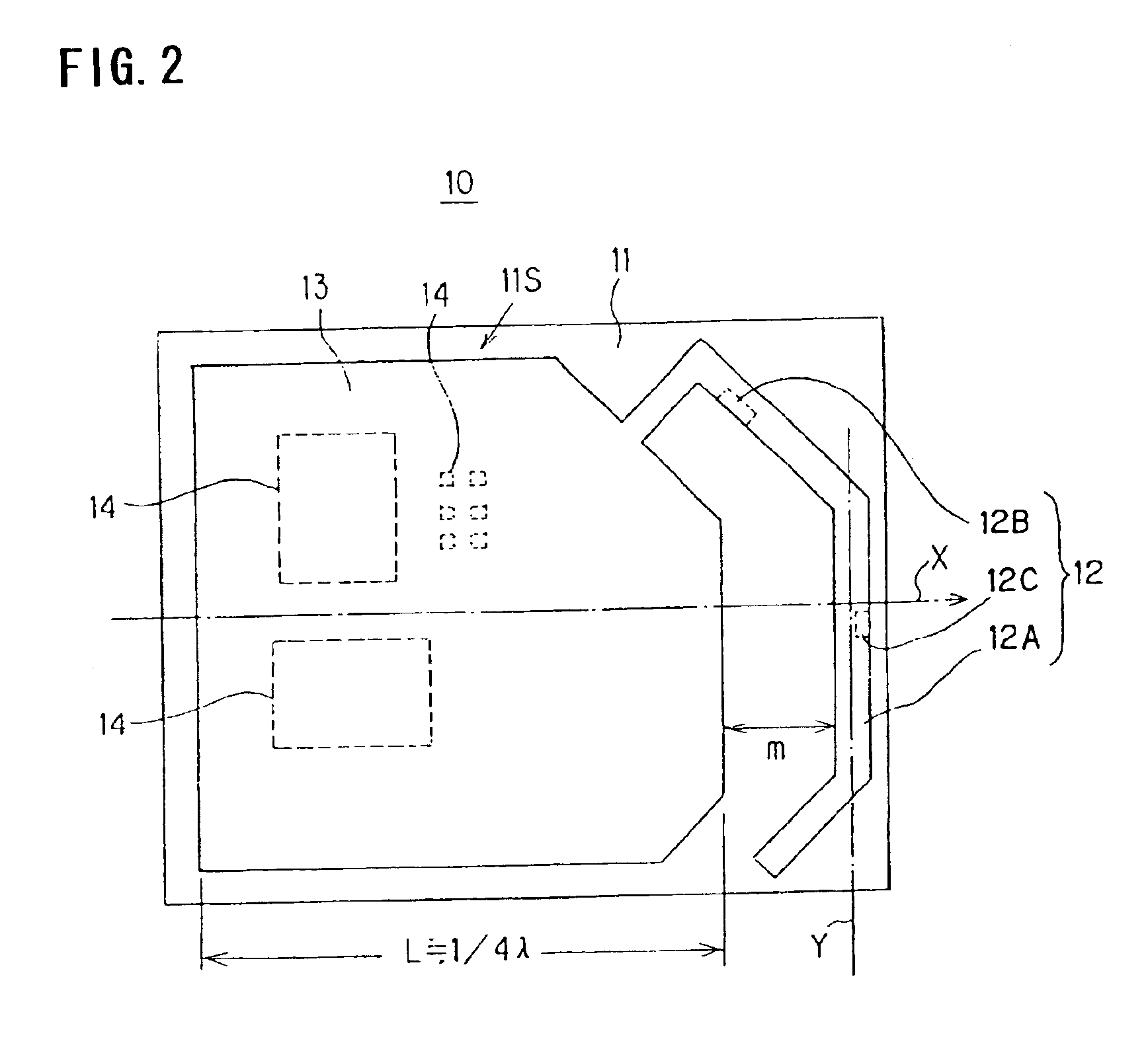
[0013]To solve the aforesaid problem, an antenna apparatus is characterized by being provided with a ground member having a length, along a predetermined directional axis, of about a quarter or more of the wavelength of an electromagnetic wave used for communication, and an antenna element disposed to extend in a direction substantially orthogonal to the directional axis, and grounded to the ground member.

Problems solved by technology

The conventional helical dipole antenna has been posing a problem in that it is large in principle, making it hardly applicable to wristwatch-size portable electronic equipment or the like required to be made smaller.
Furthermore, the inverted F antenna is constructed to implement its functions by its antenna element and ground plate (earth plate) that have a predetermined physical positional relationship, exhibiting poor freedom of layout.
In addition, the characteristics of the inverted F antenna depend on the area size of the ground plate, and decreasing the area leads to deteriorated characteristics.
Hence, there has been a problem in that, if the mounting density of components is required to increase so as to reduce the required area of a printed wiring board, then the mounting area of components uses up the area of the printed wiring board, and the area of the ground plate cannot be secured, making it impossible to obtain desired characteristics of the inverted F antenna.
To mount the chip antenna, however, a large ground area is required to obtain desired characteristics of the antenna, leading to a problem in that the entire antenna apparatus including a peripheral circuit and the ground will be large.
There is another problem of the chip antenna being expensive.

Method used


Image

  • Antenna apparatus, printed wiring board, printed circuit board, communication adapter and portable electronic equipment
  • Antenna apparatus, printed wiring board, printed circuit board, communication adapter and portable electronic equipment
  • Antenna apparatus, printed wiring board, printed circuit board, communication adapter and portable electronic equipment

Examples


modification examples

OF THE 1st THROUGH 4th EMBODIMENTS

first modification example

[0121]In the above explanation, the shielding member has covered the circuit components over the entire printed wiring board except for the portion where the antenna element is disposed. If, however, there is an allowance on a printed wiring board, it is possible to form the ground pattern electrically connected to the shielding member on the printed wiring board so as to secure the ground area by the shielding member and the ground pattern.

second modification example

[0122]In the above explanation, the antenna element has a bent configuration to fit along the shielding member. The antenna element, however, may alternatively have a curved configuration or other configurations as long as it follows the configuration of the shielding member, i.e., it has a configuration parallel with the end portion of the shielding member. In this case, it will be further effective if the microscopic current direction of the current passing through the antenna element is regarded as a vector, and the positions of the components around an antenna element pattern, a wiring pattern or a pad are set so that the foregoing vector is not parallel with the vector (microscopic current direction) of the current passing through the component, the wiring pattern or the pad as much as possible.


PUM


Abstract

An antenna apparatus is provided that includes a printed wiring board, electronic components disposed on the printed wiring board, a shielding member (ground member) that is disposed on the printed wiring board. The shielding member has a length along a predetermined directional axis X set substantially to ¼λ or more, the wavelength of an electromagnetic wave used for communication being λ. An antenna element extends in a direction crossing the directional axis X and is grounded to the shielding member (ground member).

Description

BACKGROUND OF THE INVENTION[0001]1. Technical Field[0002]The present invention relates to an antenna apparatus, a printed wiring board, a printed circuit board, a communication adapter and portable electronic equipment, and more particularly, it relates to an antenna apparatus, a printed wiring board, a printed circuit board, a communication adapter and portable electronic equipment used for high-frequency radio equipment.[0003]2. Related Art[0004]Hitherto, a helical dipole antenna has been used as an antenna for portable equipment, such as a portable telephone, which is high-frequency radio equipment.[0005]This helical dipole antenna has been constructed such that it is drawn out of the housing of portable equipment when it is used or it has been used while it is accommodated in the housing.[0006]Japanese Unexamined Patent Application Publication No. 3-175826 discloses an antenna assembly having a second antenna in the housing of portable equipment separately from a helical dipole ...

Claims


Application Information

Patent Timeline
IPC IPC(8): H01Q1/00H01Q9/42H01Q1/52H01Q23/00H01Q9/04H01Q1/24H01Q1/22H01Q13/08H01Q1/38H01Q1/44H01Q9/40
CPCH01Q1/243H01Q1/526H01Q9/0421H01Q9/42H01Q23/00H01L2924/3025H01L2924/19105H01L2223/6677H01Q1/44
Inventor KOYAMA, SHUNSUKE
Owner SEIKO EPSON CORP
Learn More