Image forming method and apparatus

a technology of image forming and forming method, which is applied in the direction of electrographic process apparatus, instruments, optics, etc., can solve the problems of insufficient toner supply, low image density, and extremely bad fluidity, and achieve the effect of high quality

Inactive Publication Date: 2005-09-20
RICOH KK
View PDF10 Cites 34 Cited by
  • Summary
  • Abstract
  • Description
  • Claims
  • Application Information

AI Technical Summary

Benefits of technology

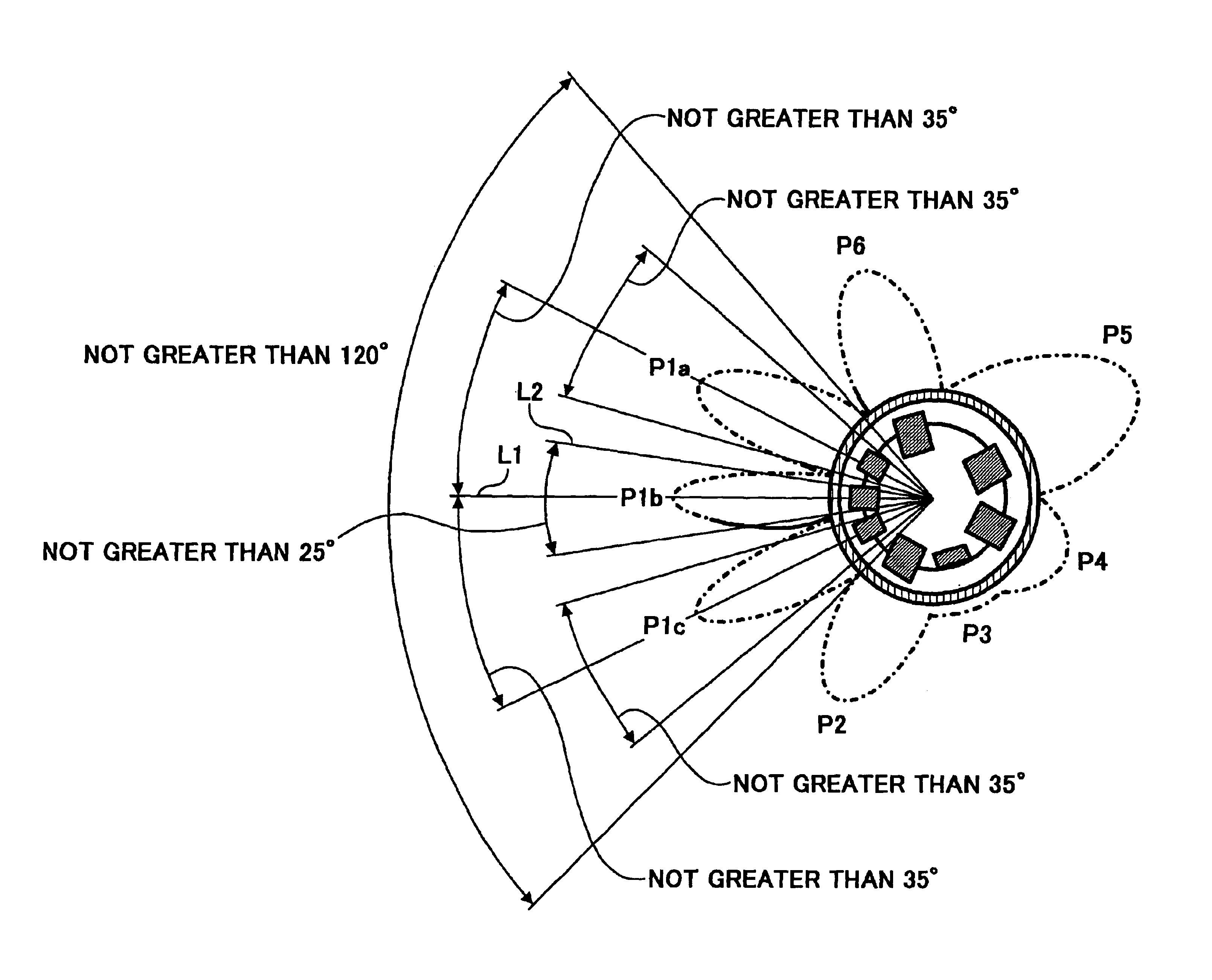
[0017]Accordingly, an object of the present invention is to provide an image forming method and apparatus by which high quality images are produced for a long period of time without causing the rear-end omission problem.

Problems solved by technology

However, in such a high-efficiency developing method in which a magnetic force of a main development magnetic pole is high, and a developer having a short length of magnet brush rubs a surface of a photoreceptor at a rotating speed of from 1.1 to 3.0 times that of the photoreceptor, the toner is insufficiently supplied i.e., the resultant images have a low image density or the resultant images are unclear when the rotating speed is less than 1.5 times. Therefore the rotating speed ratio is preferably not less than 1.5 times. In this case, a rear-end omission problem in that the rear end of a solid image is omitted occurs.
Such a problem tends to be caused under a condition in which the rotating speed ratio is greater than 1.0.
This problem is seriously caused as the rotating speed of the magnetic brush increases.
However, since fine toner particles have extremely bad fluidity (characteristic specific to a fine powder), the fine toner particles adhered to the, developing sleeve are hardly re-adhered to the carrier surface.
Namely, since an electrically insulating layer constituted of a toner ingredient is formed on a surface of an electroconductive sleeve, the effective bias of the developing bias applied lowers, and thereby the developing ability of the developing sleeve is deteriorated.
The adhesion of a toner to a sleeve can be prevented to some extent by this method, but the ability of the sleeve to feed a developer is not enough for current fast printing machines, and high quality images cannot be obtained easily.
When the filming phenomenon occurs on the carrier (i.e., a spent carrier problem), the toner cannot be friction-charged with such a carrier.
As a result, defective charging occurs and the resultant images have background fouling.
In addition, a white stripe abnormal image appears on a halftone image when a wax film is formed on a photoreceptor.
In addition, waxes tend to cause the on-sleeve toner fixation.
These phenomena turn worse, i.e., it is difficult to maintain the initial image qualities, when copying processes are repeated.
In addition, it is known that temperature increases in a developing apparatus with repetition of copying processes, resulting in increase of the atmospheric temperature at a nip region.
As a result, the wax in the toner easily bleeds out, resulting in occurrence of fixation of the wax on the sleeve, and filming of the wax on the photoreceptor and the carrier used.

Method used


Image

  • Image forming method and apparatus
  • Image forming method and apparatus
  • Image forming method and apparatus

Examples


example 1

Preparation of Fine Particles Dispersion (1)

[0155]The following components were placed in a reacting container having a stirrer and a thermometer and rotated at a speed of 400 rpm for 15 minutes to prepare a white emulsion.

[0156]

Water683partsSodium salt of sulfate of ethylene oxide adduct of11partsmethacrylic acid (ELEMINOL RS-30, manufactured bySanyo Chemical Industries Ltd.)Styrene83partsMethacrylic acid83partsButyl acrylate110partsAmmonium persulfate1part

[0157]The emulsion was heated to 75° C. and reacted for 5 hours. Further, 30 parts of a 1% aqueous solution of ammonium persulfate was added and aged for 5 hours to prepare an aqueous dispersion of a vinyl resin (styrene-methacrylic acid-butyl acrylate-sodium salt of sulfate of ethylene oxide adduct of methacrylic acid copolymer. A volume average particle diameter of the fine particle dispersion (1) was 0.10 μm when measured with LA-920. A part of the fine particle dispersion (1) was dried to isolate a resin portion. The glass tr...

examples 3 to 5

[0199]The dispersion diameter of the wax in the toner can be controlled by changing agitating condition of the components when the oil phase was prepared. The wax concentration in the surface portion and outer portion can be controlled by changing the aging temperature and time in the emulsifying process.

[0200]Accordingly, by appropriately changing the above-mentioned conditions, toners C, D and E having different wax concentration in the surface portion (from 0 to 1 μm) and the outer portion thereof were prepared. In addition, the procedure for preparation of the carrier in Example 1 was repeated.

example 6

[0201]The procedure for preparation of the toner and the two-component developer in Example 1 were repeated except that the ester wax was replaced with a carnauba wax subjected to a treatment of removing a free aliphatic fatty acid. Thus a toner F, and a developer including the toner F were prepared.

[0202]The physical properties of the above-prepared toners are shown in Table 1.

[0203]

TABLE 1Content ofContent ofWax area inwaxfinethe surfaceWaxparticlesparticlesportion ofexisting inhavingVolumehaving athe tonerthe outerdispersionaveragediameter nothaving aportion ofdiameter ofparticlegreater thandepth ofthe tonerfrom 0.5 todiameter2 μmfrom 0 to 1 μm(% by3.0 μm(μm)(% by number)(%)number)(% by number)Ex. 15.513.0356050(Toner A)Ex. 25.519.5335545(Toner B)Ex. 35.519.0255068(Toner C)Ex. 45.519.0226858(Toner D)Ex. 55.519.0357575(Toner E)Ex. 65.519.0258095(Toner F)Comp. Ex. 13.028.5308772(Toner G)Comp. Ex. 28.013.5308780(Toner H)Comp. Ex. 36.023.0657740(Toner I)Comp. Ex. 47.545.0409055(Toner...


PUM


Abstract

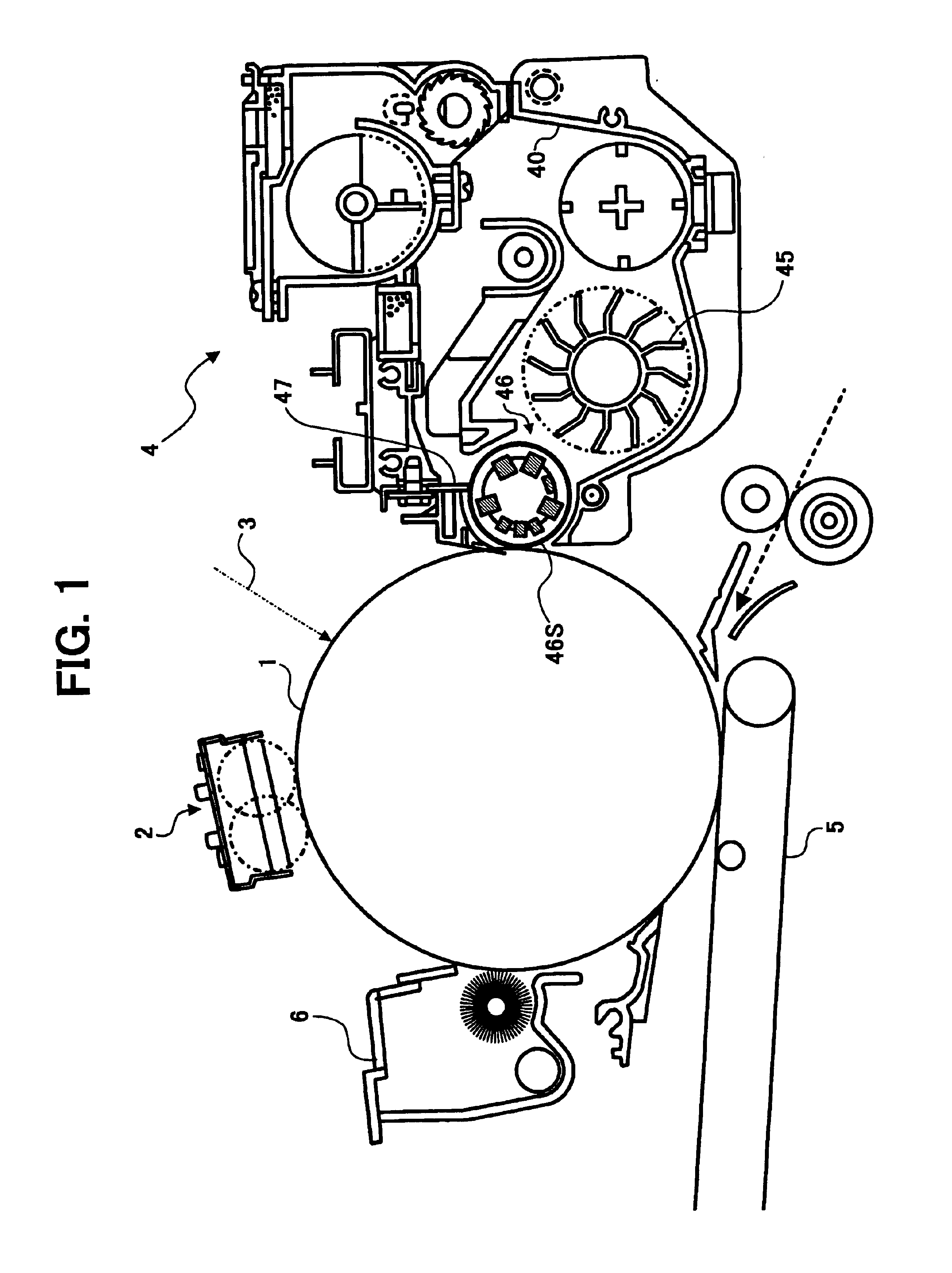
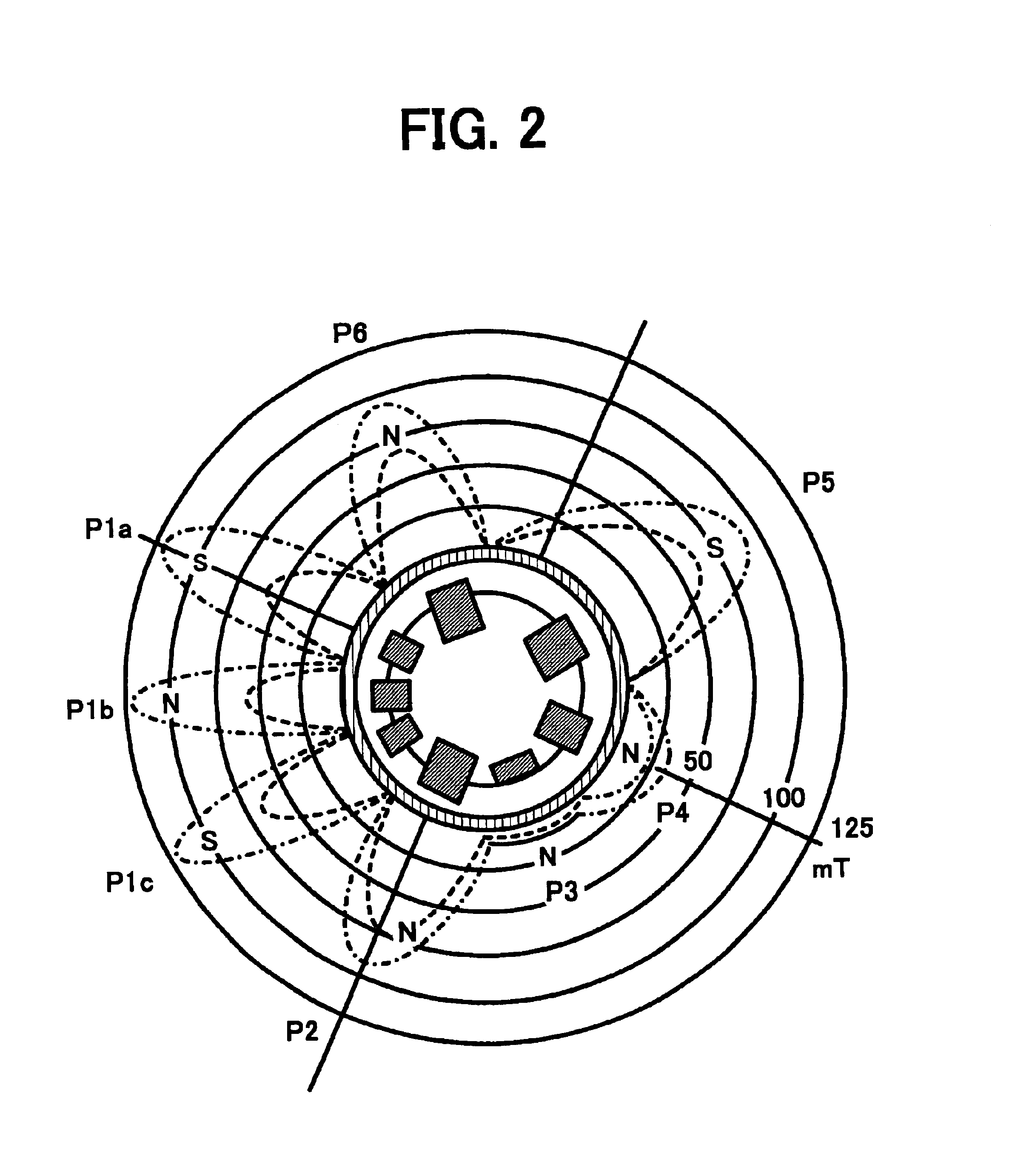
A method for developing an electrostatic latent image, including forming a magnet brush of a developer including a toner and a carrier on a developing sleeve including a main magnet and auxiliary magnets; and developing the electrostatic latent image with the magnet brush to form a toner image at a rubbing region, wherein the magnetic flux density in a normal line direction, half width, and attenuation ratio of the main magnet and the angle between the main magnet and auxiliary magnets are specified, and the magnetic sleeve has specific grooves thereon, and wherein the toner has a volume average particle diameter of from 4.0 to 7.0 μm, and includes fine particles having a circle equivalent diameter not greater than 2 μm in an amount not greater than 20% by number.

Description

BACKGROUND OF THE INVENTION[0001]1. Field of the Invention[0002]The present invention relates to an image forming method and an image forming apparatus. Specifically, the present invention relates to a method for developing an electrostatic latent image with a developer, and to a developing apparatus including magnetic poles for forming a magnetic brush of a developer in a developing region on a surface of a developer bearing member. In addition, the present invention also relates to a process cartridge which produces images using a toner, and a method for fixing a toner image.[0003]2. Discussion of the Background[0004]Copiers, printers, facsimile apparatus and similar electrophotographic or electrostatic image forming apparatus generally include a latent image bearing member such as photoconductive drums or photoconductive belts. A latent image is formed on the image bearing member in accordance with image data. It is popular to use a magnet brush developing method using a two-comp...

Claims


Application Information

Patent Timeline
Patent Type & Authority Patents(United States)
IPC IPC(8): G03G15/09
CPCG03G15/0921
Inventor KONDO, MAIKOSASAKI, FUMIHIRONANYA, TOSHIKIYAGI, SHINICHIROTOMITA, MASAMIEMOTO, SHIGERUSHIMOTA, NAOHITOHIGUCHI, HIROTOICHIKAWA, TOMOYUKI
Owner RICOH KK
Why Eureka
Try Eureka