
Communication method and common control bus interconnecting a controller and a precision measurement assembly

a communication method and precision measurement technology, applied in the field of precision measurement tools, can solve the problems of limited servo performance, large number of wires, and introduction of significant imprecision in measurement, and achieve the effect of reducing cable drag in the energy track

Inactive Publication Date: 2005-09-27
HEXAGON TECH CENT GMBH
View PDF9 Cites 53 Cited by
  • Summary
  • Abstract
  • Description
  • Claims
  • Application Information

AI Technical Summary

Benefits of technology

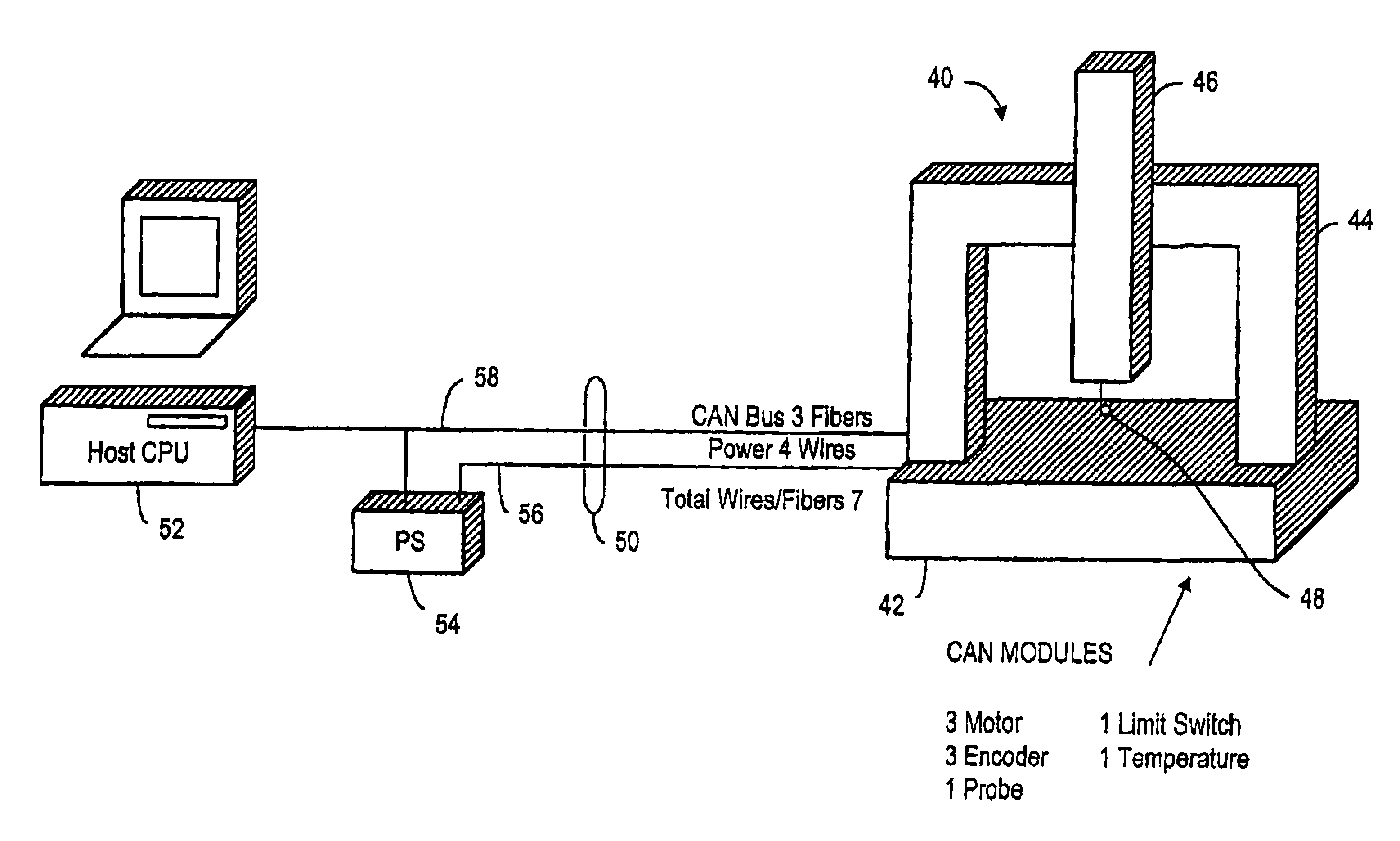
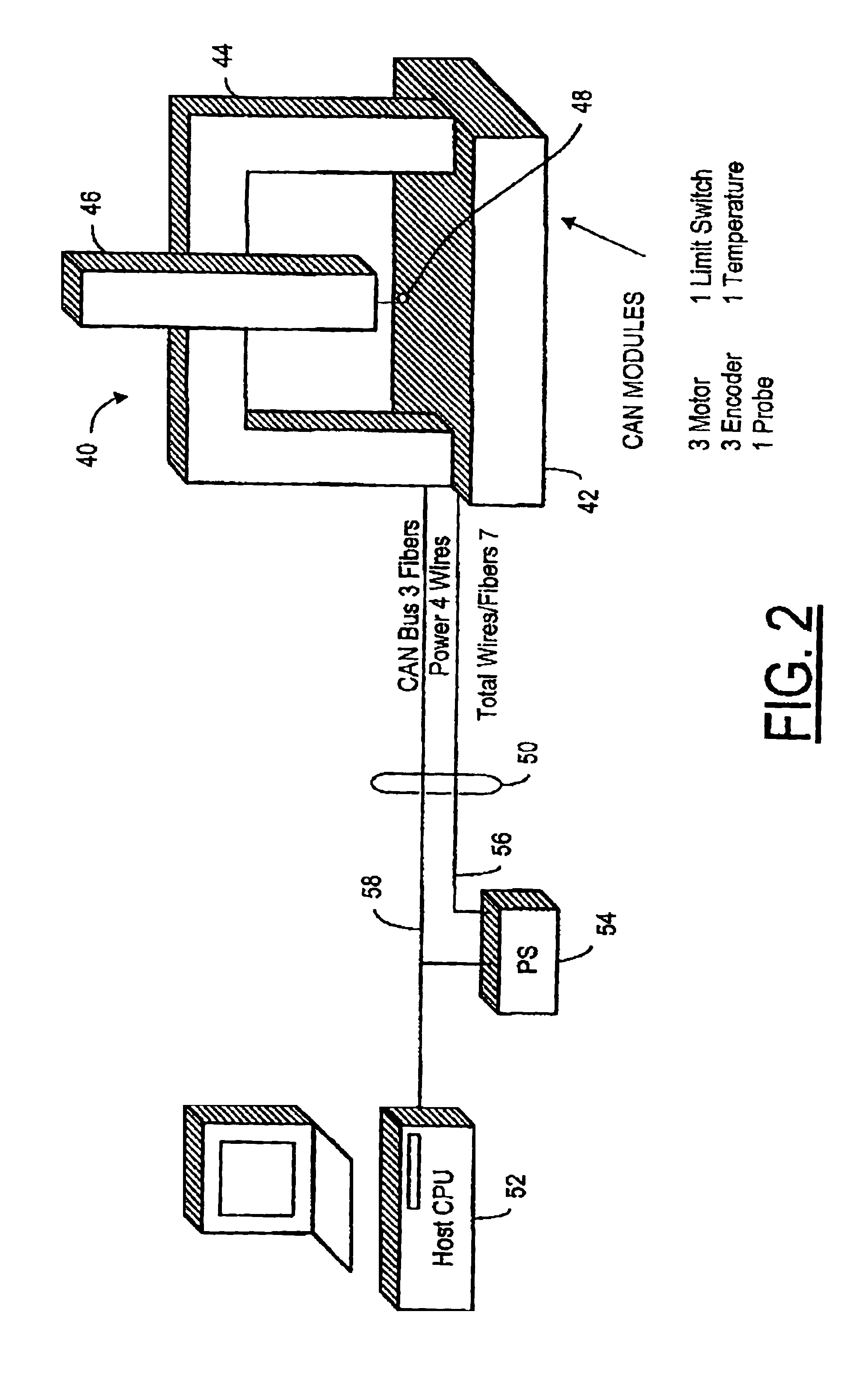
The present invention provides an apparatus and method for reducing cable drag and improving servo performance in a precision measurement assembly. The apparatus includes a platform for supporting an object, a probe for moving in multiple axes along a path on the surface of the object, and a controller for controlling the movement of the probe. The controller is connected to a shared bus that includes sensed position signals from position sensors mounted on the platform and actuator control signals for the probe. The shared bus is made at least in part by optical fibers and includes a synchronization line. The invention achieves a reduction in cabling and increases measuring performance by using state-of-the-art concepts such as fiber optics, distributed / modular controls, and digital signal processing. The technical effects of the invention include improved accuracy, reduced service costs, and improved efficiency of the measurement process.

Problems solved by technology

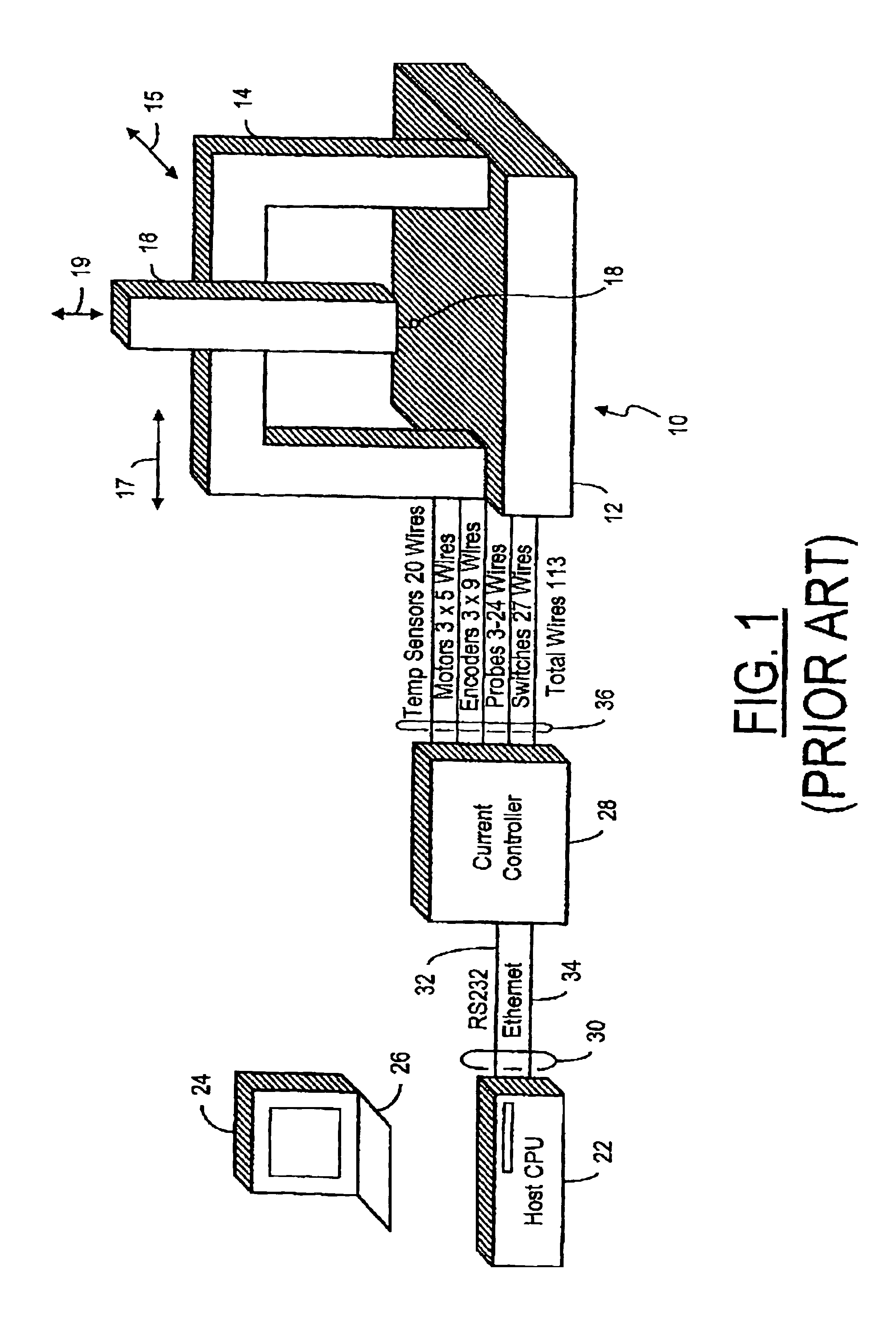
One of the disadvantages of having the controller separate from the precision measurement assembly 10 is that numerous wires 36 have to be utilized to interconnect the controller to the precision measurement assembly 10, particularly the bridge or other equivalent first moveable part.
The large number of wires creates a significant cable drag problem in view of the fact that even the very slightest twist in the bridge caused by such drag will cause a deformation from the mathematical model of the ideal system to such an extent that a significant imprecision in the measurement is introduced.
Another problem is limited servo performance which it will be desirable to improve.

Method used


Image

  • Communication method and common control bus interconnecting a controller and a precision measurement assembly
  • Communication method and common control bus interconnecting a controller and a precision measurement assembly
  • Communication method and common control bus interconnecting a controller and a precision measurement assembly

Examples


Embodiment Construction

[0022]Referring now to FIG. 2, a precision measurement assembly 40 is shown having a platform 42, a first moveable part 44, in this case a bridge 44, one or more carriers 46 and a probe 48. Not shown but mounted on or within the precision measurement assembly 40 are various modules such as three motor modules for connection to one or more actuator motors each, three encoder modules for connection to one or more encoders each, a probe module for connection to the probe 48, a limit switch module for connection to one or more limit switches and a temperature module for connection to one or more temperature probes. These modules may be interconnected using a standard bus such as a known or custom serial network bus, e.g., a CAN (Controller Area Network) bus as shown or a nonstandard bus. CAN is a known serial bus system with multi-master capabilities according to ISO 11898. Using a shared or common bus allows an interconnection 50 between the assembly 40 and a host 52 to be much reduced...


PUM


Abstract

The number and weight of wires interconnecting a host and / or controller with a precision measurement assembly is reduced using a common or shared bus. The bus may be entirely electrical or may include optical fibers to reduce EMI susceptibillty. A custom bus or a known serial network bus such as CAN or SIRCOS may be used.

Description

CROSS-REFERENCE TO RELATED APPLICATION[0001]This as the national stage of International Application No. PCT / IB02 / 02154, filed Jun. 11, 2002, as amended on Jan. 10, 2003, which was published in English Dec. 19, 2002, under International Publication No. WO 02 / 101323 A2 and republished in English Jun. 12, 2003 under International Publication No. WO 02 / 101323 A3 with the amendment of Jan. 10, 2003 and which claims priority from U.S. Provisional Application Ser. No. 60 / 297,480, filed Jun. 12, 2001.BACKGROUND OF THE INVENTION[0002]1. Technical Field[0003]The present invention relates to precision measurement tools and, more particularly, to a shared control bus between a host and a precision measurement assembly.[0004]2. Discussion of Related Art[0005]Precision measurement tools include coordinate measuring machines (CMM), precision measuring instruments and the like. CMMs range from bench top and articulated arm manual CMMs to high-speed DCC scanning machines, gantries, shop floor measur...

Claims


Application Information

Patent Timeline
Patent Type & Authority Patents(United States)
IPC IPC(8): G01B21/02G01B21/04G01B21/00G08C15/00
CPCG01B21/04G05B2219/33218G05B2219/37193G05B2219/40237
Inventor RUSSELL, GARY W.
Owner HEXAGON TECH CENT GMBH
Learn More