Grinding assembly, grinding apparatus, weld joint defect repair system, and methods

a technology of weld joint and assembly, which is applied in the direction of edge grinding machines, grinding machine components, manufacturing tools, etc., can solve the problems of undesirable liquid use inside the hot cell, machining process problems, and insufficient hot cell use of current grinding systems

Inactive Publication Date: 2005-09-27
BATTELLE ENERGY ALLIANCE LLC
View PDF6 Cites 38 Cited by
  • Summary
  • Abstract
  • Description
  • Claims
  • Application Information

AI Technical Summary

Benefits of technology

[0013]In yet another aspect, a weld joint defect repair system includes an inspection assembly having a first processor in communication therewith, the inspection assembly is configured to inspect weld joints of a workpiece to identify weld joint defects. The system includes a grinding assembly having a grinding apparatus and second processor in communication therewith, the second processor is configured to receive information related to the weld joint defects from the first processor. The second processor is further configured to create a distinct contour grinding profile based on the received information. The grinding apparatus includes a grinding wheel configured to grind the weld joints to rectify the weld joint defects, a removably attachable member configured to detachably receive individual ones of a plurality of tools including the grindin

Problems solved by technology

Machining processes present problems because cutting fluid or other lubricants may have to be used with tools for the machining processes.
Usage of liquids inside the hot cell is undesirable as such a step introduces waste into the hotcell, and therefore additional steps may have to be undertaken to dispose the newly introduced waste products.
However, current grinding systems are inadequate for use in hot c

Method used


Image

  • Grinding assembly, grinding apparatus, weld joint defect repair system, and methods
  • Grinding assembly, grinding apparatus, weld joint defect repair system, and methods
  • Grinding assembly, grinding apparatus, weld joint defect repair system, and methods

Examples


Embodiment Construction

[0022]This disclosure of the invention is submitted in furtherance of the constitutional purposes of the U.S. Patent Laws “to promote the progress of science and useful arts” (Article 1, Section 8).

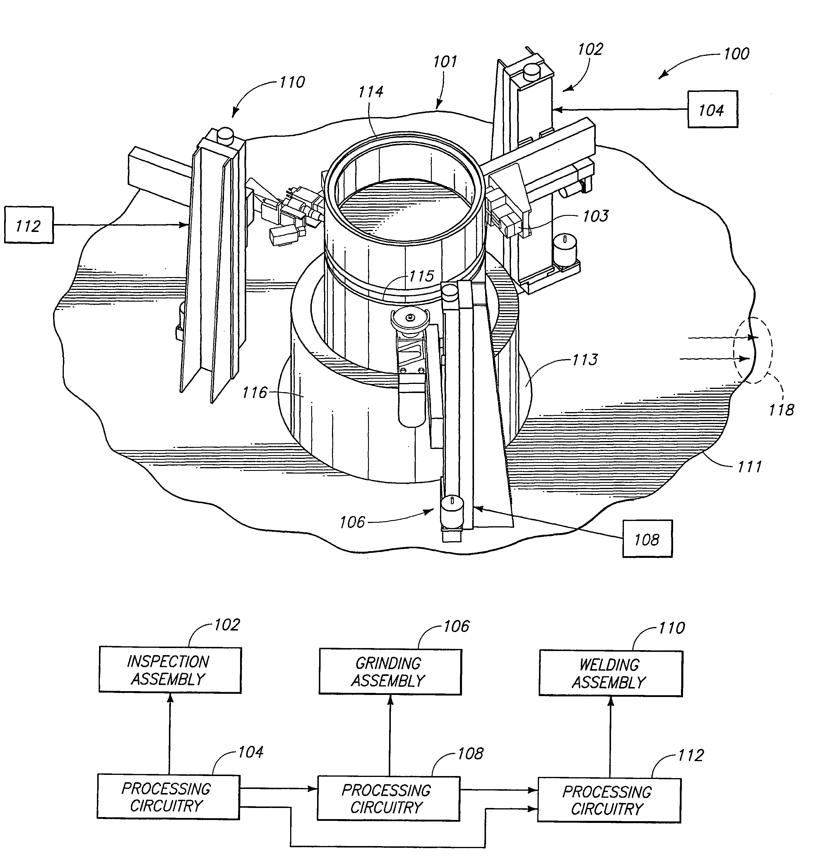
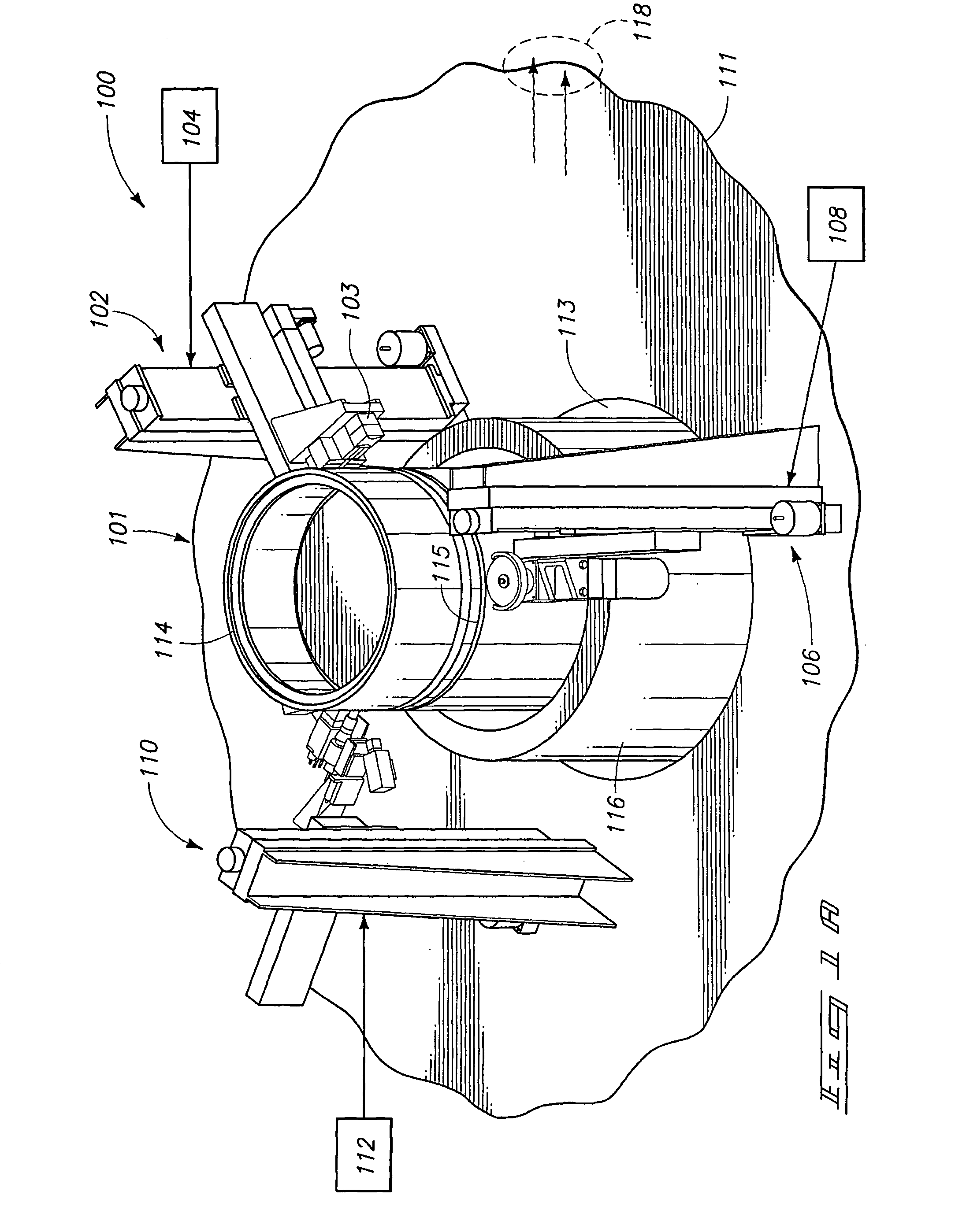
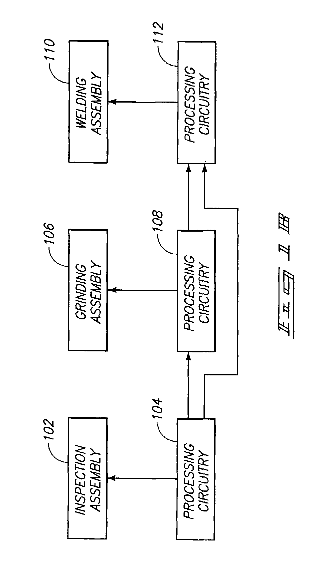
[0023]FIG. 1A is a schematic of an overall system 100 configured to inspect (e.g., non-destructive examination) and repair (e.g., grind, weld) a workpiece (e.g., waste canister) in accordance with various aspects of the invention. More particularly, the system 100 includes a room, such as a hot cell, 101, an inspection assembly 102 having inspection apparatus 103 and a processing circuitry 104, a grinding assembly 106 having a processing circuitry 108, and a welding assembly 110 having a processing circuitry 112. The respective processing circuitry 104, 108, and 112 are alternatively referred to herein as control computer. The processing circuitry 104, 108, 112 may be located inside or outside of the room 101. Although shown as distinct components in FIG. 1A, the processing circuitry 104,...


PUM

PropertyMeasurementUnit
Speedaaaaaaaaaa

Abstract

A grinding assembly for grinding a weld joint of a workpiece includes a grinder apparatus, a grinder apparatus includes a grinding wheel configured to grind the weld joint, a member configured to receive the grinding wheel, the member being configured to be removably attached to the grinder apparatus, and a sensor assembly configured to detect a contact between the grinding wheel and the workpiece. The grinding assembly also includes a processing circuitry in communication with the grinder apparatus and configured to control operations of the grinder apparatus, the processing circuitry configured to receive weld defect information of the weld joint from an inspection assembly to create a contour grinding profile to grind the weld joint in a predetermined shape based on the received weld defect information, and a manipulator having an end configured to carry the grinder apparatus, the manipulator further configured to operate in multiple dimensions.

Description

GOVERNMENT RIGHTS[0001]This invention was made with Government support under Contract DE-AC07-991D13727 awarded by the U.S. Department of Energy. The Government has certain rights in the invention.TECHNICAL FIELD[0002]The invention relates to grinding apparatus and methods. Some aspects of the invention relate more particularly to automated grinding apparatus for use in hazardous environments.BACKGROUND OF THE INVENTION[0003]Hazardous materials are typically sealed in canisters for long term storage and to prevent such materials from escaping into the environment. The sealing of canisters for long term storage of high level nuclear waste requires equipment that can be remotely operated with little or no intervention by personnel. Such canisters carrying nuclear waste or other hazardous materials are typically remotely closed, welded, and then inspected before being approved for long term storage. Welding and inspection of such canisters is performed in a hot cell to limit exposure o...

Claims


Application Information

Patent Timeline
IPC IPC(8): B24B49/00B24B5/04
CPCB24B5/047B24B49/00B23K31/125
Inventor LARSEN, ERIC D.WATKINS, ARTHUR D.BITSOI, RODNEY J.PACE, DAVID P.
Owner BATTELLE ENERGY ALLIANCE LLC
Why Eureka
Try Eureka