Ureteral stent with end-effector and related methods

a ureteral stent and end-effector technology, applied in the field of ureteral stents, can solve the problems of threatening renal function, ureteral stents, and urinalysis, and achieve the effects of reducing fluid retention, less irritation, and minimizing patient discomfor

Inactive Publication Date: 2005-09-27
BOSTON SCI SCIMED INC
View PDF69 Cites 82 Cited by
  • Summary
  • Abstract
  • Description
  • Claims
  • Application Information

AI Technical Summary

Benefits of technology

[0009]It is therefore an object of this invention to provide a more comfortable ureteral drainage device providing an end-effector, including a balloon at the proximal portion of a stent that will be less irritating that a typical indwelling stent. When positioned within the ureter of a mamm

Problems solved by technology

Serious obstructions of the urinary tract may cause urine to back up into the kidney, threatening renal function.
The trigone has greater pain sensation relative to other regions of the bladder wall and is a major source of patient discomfort when the typical indwelling stent is in contact with this region of the bladder.
Ureteral stents, particularly the portion positioned in the ureter and the bladder, may produce adverse effects including hemorrhage, a continual urge to urinate, flank pain accompanying reflux of urine back up the ureter

Method used


Image

  • Ureteral stent with end-effector and related methods
  • Ureteral stent with end-effector and related methods
  • Ureteral stent with end-effector and related methods

Examples


Embodiment Construction

[0029]The invention generally concerns a drainage device that, when positioned within the ureter of a mammal, assists in reducing fluid retention by facilitating the drainage of urine from the kidney through the ureter and into the urinary bladder while simultaneously minimizing patient discomfort. A common feature of the invention is a proximal end-effector, including a balloon. Throughout the discussion of the illustrative embodiments, it is to be understood that in the figures, like reference characters generally refer to the same parts throughout different views.

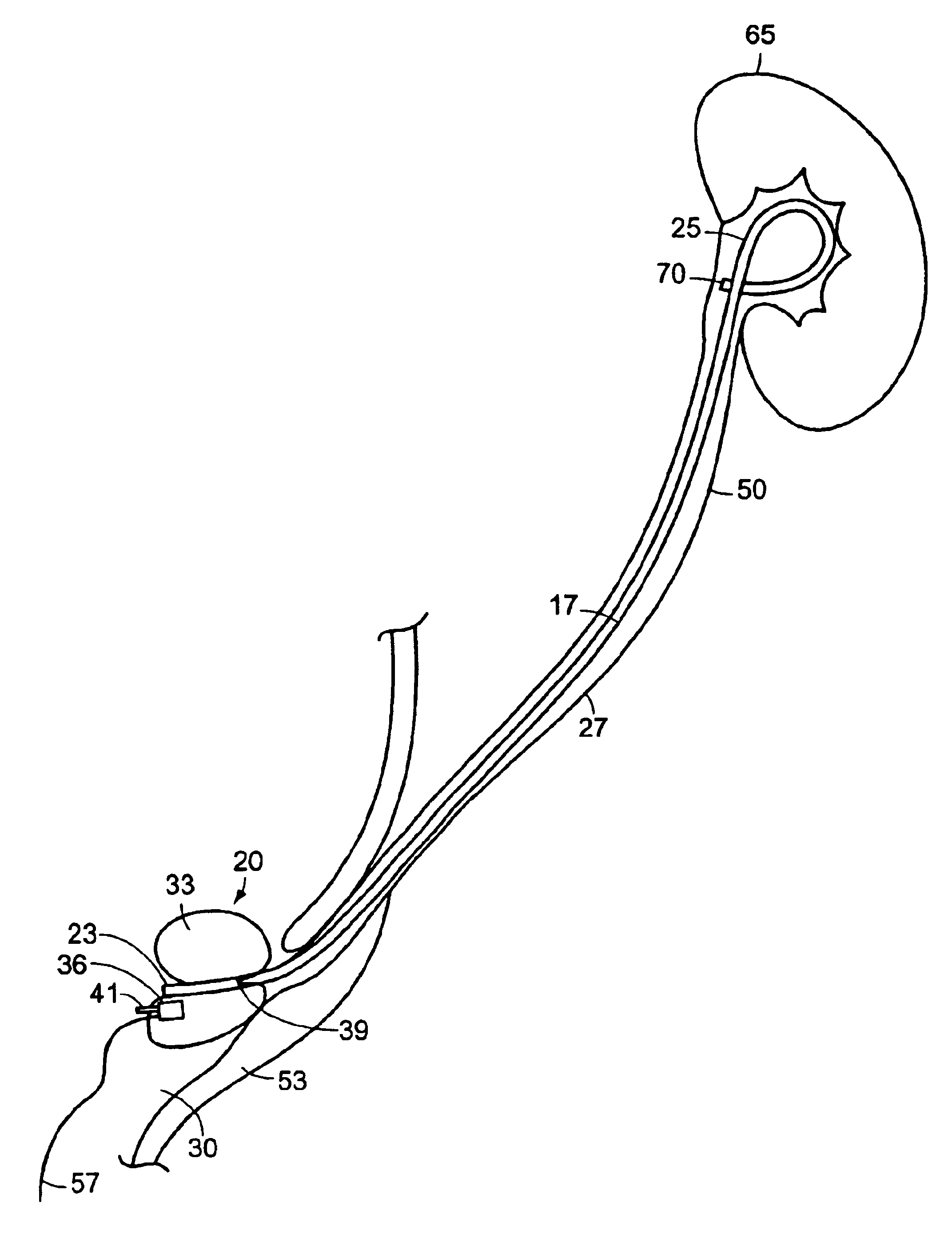
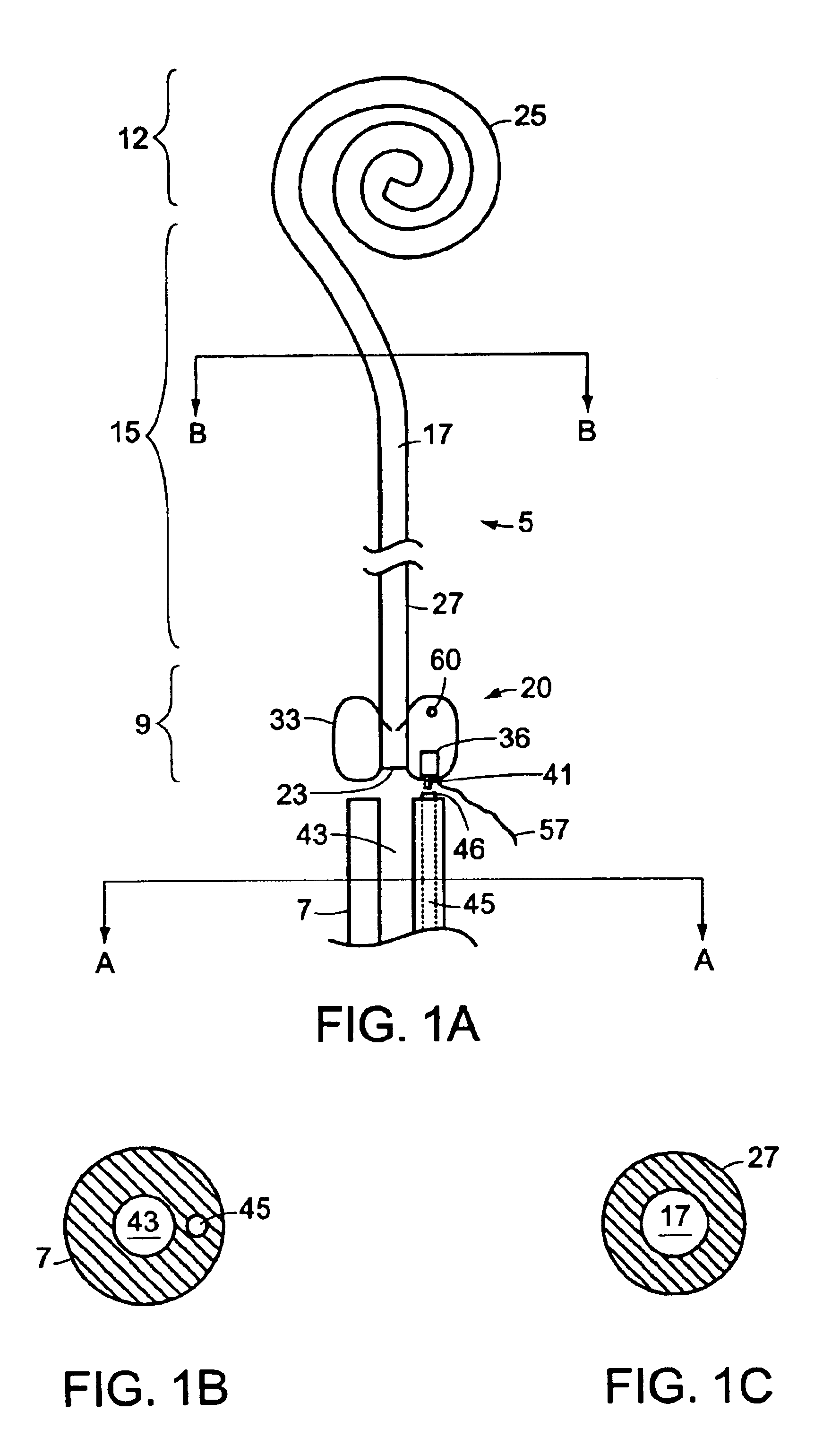
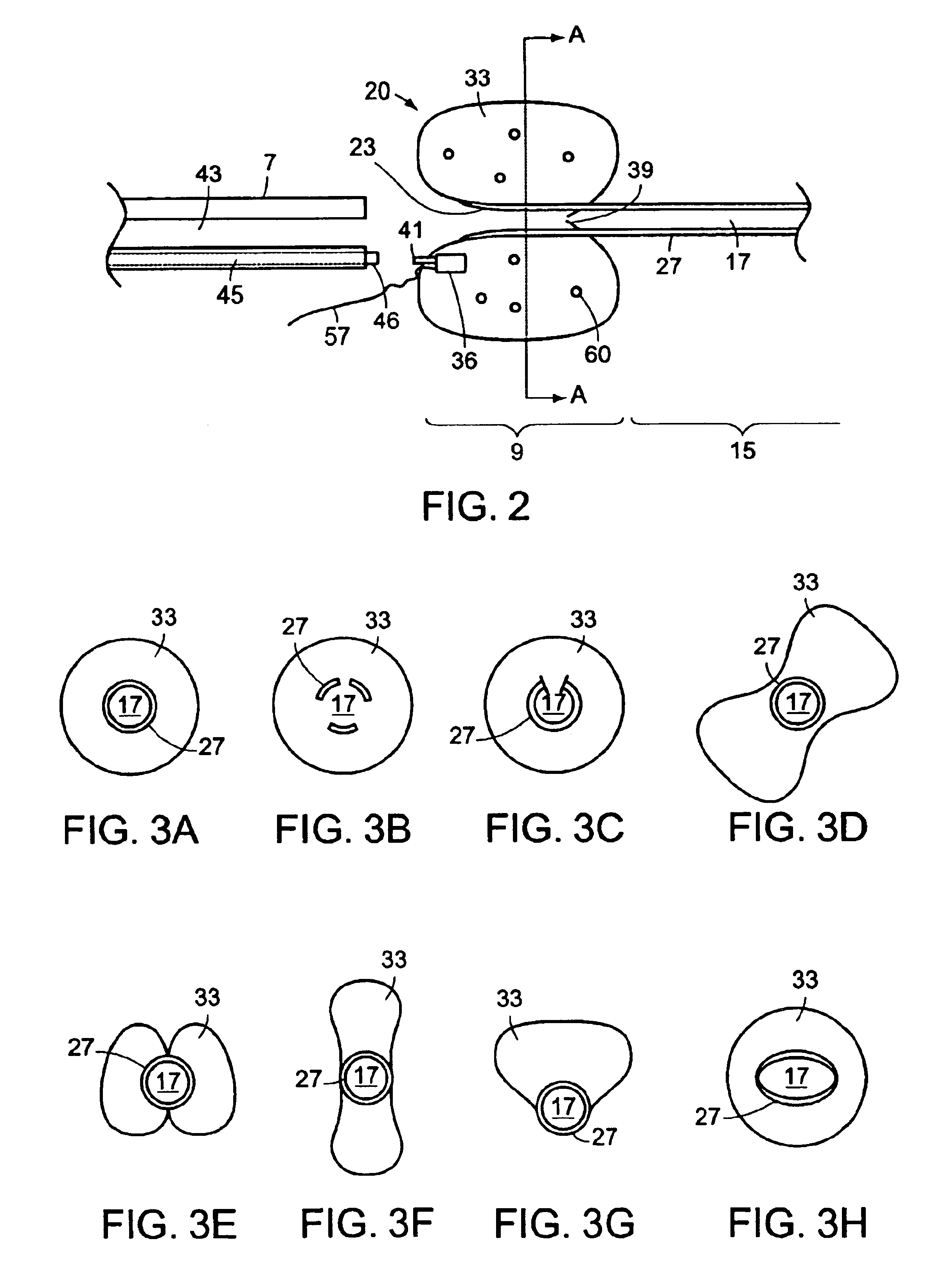
[0030]Referring to FIGS. 1A-1C, a ureteral stent system comprising a ureteral stent 5 and pusher tube 7 according to the invention, in general, is shown. The stent 5 is suitable for use with the pusher tube 7 for implantation within the ureter of a patient, and includes a proximal portion 9, a distal portion 12, and an elongated body portion 15 defining a lumen 17 which extends between the proximal portion 9 and the dist...


PUM


Abstract

A system and related methods for maintaining the patentcy of the ureter comprising a pusher tube having a pusher tube lumen and an inflate lumen disposed within a wall of the pusher tube and a urinary stent having a proximal and distal portions with an elongated body portion therebetween configured to fit the ureter of the patient and defining a lumen. The system further includes an end-effector that may comprise an inflatable balloon positioned at the proximal portion of the urinary stent for retaining the proximal portion in the urinary bladder. At the distal portion, a retention end-piece is positioned for retaining the distal portion of the stent in the renal pelvis. The end-effector and the retention end-piece of the stent maintain the elongated body portion in situ. The end-effector may also include an inflatable balloon and may contain pharmaceutical or biologic agents for controlled release into the bladder.

Description

FIELD OF THE INVENTION[0001]This invention generally relates to stents and more particularly to ureteral stents.BACKGROUND[0002]Ureteral stents are used to create a pathway for urinary drainage from the kidney to the bladder in patients with ureteral obstruction or injury or to protect the integrity of the ureter in a variety of surgical manipulations. A number of clinical conditions can produce interruption in urine flow including, for example, intrinsic obstruction of the ureter due to tumor growth, stricture or stones, compression of the ureter due to extrinsic tumor growth, stone fragment impactation in the ureter following extracorporeal shock wave lithotripsy (ESWL), and ureteral procedures such as ureteroscopy and endopyelotomy. Stents may be used to treat or avoid obstructions of the ureter (such as ureteral stones or ureteral tumors) that disrupt the flow of urine from the corresponding kidney to the urinary bladder. Serious obstructions of the urinary tract may cause urine...

Claims


Application Information

Patent Timeline
IPC IPC(8): A61F2/04A61M25/00
CPCA61F2/04A61M27/008A61F2002/048A61M2025/105
Inventor ROBERTSON, DAVID W.
Owner BOSTON SCI SCIMED INC
Why Eureka
Try Eureka