Transverse flux electrical machine with toothed rotor

a technology of electrical machines and rotors, which is applied in the direction of magnetic circuit rotating parts, magnetic circuit shapes/forms/construction, propulsion systems, etc., can solve the problems of increasing the magnetic leakage flux between two adjacent magnets, reducing the converted power per weight unit of the machine, and difficulty in producing the rotor, etc., to achieve easy reduction of air gap distance, increase the mechanical rigidity of the rotor and the stator, and increase the power

Inactive Publication Date: 2005-09-27
EOCYCLE TECH
View PDF19 Cites 55 Cited by
  • Summary
  • Abstract
  • Description
  • Claims
  • Application Information

AI Technical Summary

Benefits of technology

[0012]First, production of the rotor is facilitated, thanks to the presence of slots and teeth defining a toothed magnetic structure, providing natural mechanical guides for the insertion of the magnetic blocks of the rotor.
[0026]According to another aspect of the present invention, the invention concerns a transverse flux electrical machine with alternating single phase current, comprising magnetic parts inserted inside the rotor structure, that contains toothed guides, the guides allowing an easy insertion and a retention of said magnetic parts.

Problems solved by technology

U.S. Pat. No. 5,854,521 presents a transverse flux machine without flux concentration where the stator is located on one side only of the rotor, but where the magnets are magnetized perpendicularly to the direction of rotation of the rotor, which increases magnetic leakage fluxes between two adjacent magnets, and consequently decreases the converted power per weight unit of the machine.
The main problems of the transverse flux machine with flux concentration of the prior art are the following.
Production of the rotor is difficult, because the magnetic flux concentrators must be fixed to a disc or a common rotor ring by means of bolts and nuts.

Method used


Image

  • Transverse flux electrical machine with toothed rotor
  • Transverse flux electrical machine with toothed rotor
  • Transverse flux electrical machine with toothed rotor

Examples


Embodiment Construction

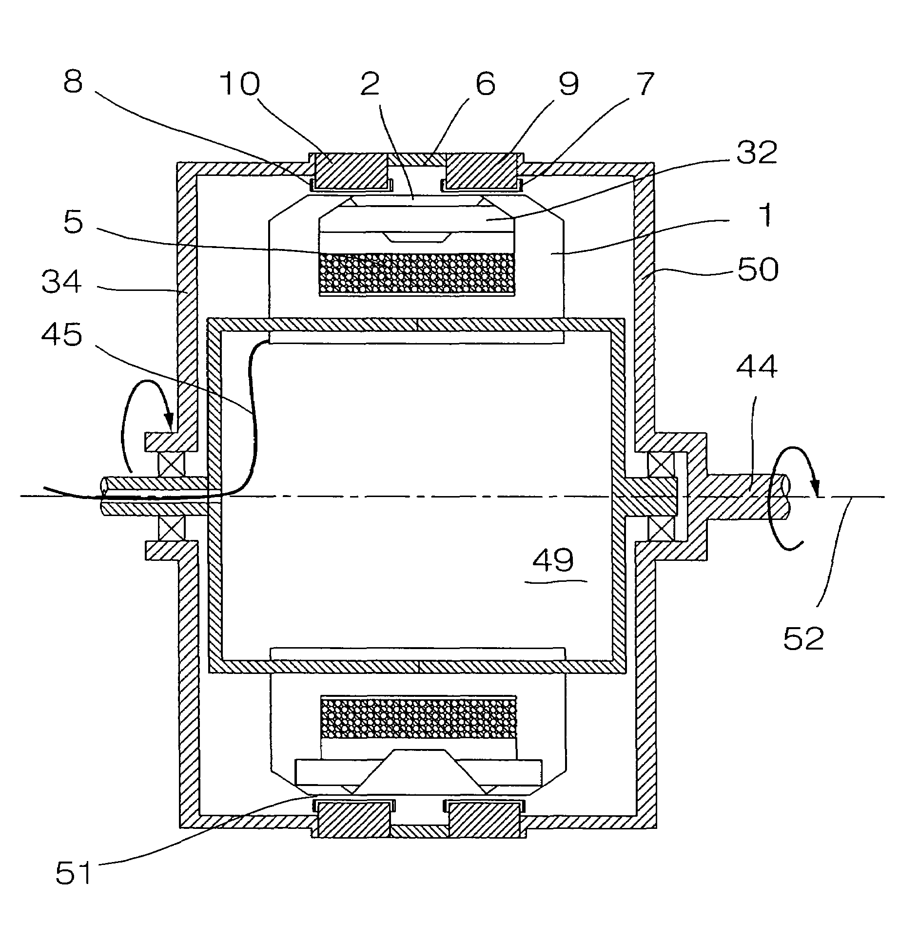
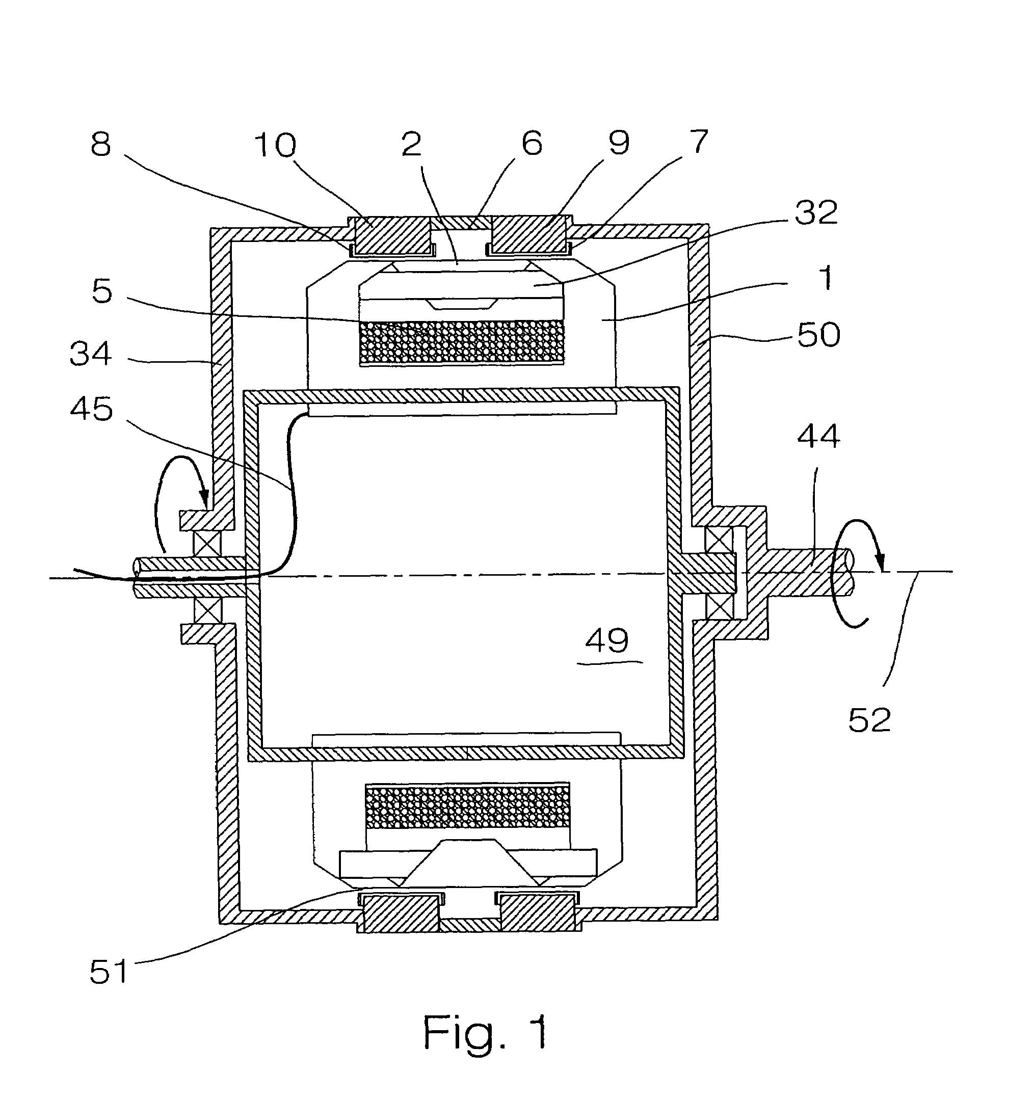
[0035]In FIG. 1, the transverse flux machine of a preferred embodiment of the invention is illustrated in a configuration where stator 49 is located at a shorter distance from the rotation axis 52 of the machine in the radial direction, than rotor 50. Rotor 50 is exterior and rotates around stator 49, that is interior. Electrical connections 45 of the stator run through the rotation axis 44 of the stator, the latter being fixed. An air gap 51 is present between magnetic flux concentrators 7 and 8 and soft iron cores 1 and 2. Supporting cylinder 34 serves to hold the rotor.

[0036]Toothed magnetic structures 9 and 10 define cylinders, that can be kept together by means of non-magnetic insulating material 6 (by passing non-magnetic rods connecting elements 6, 9 and 10 together). This assembly 6, 9 and 10 must be connected to the rotation shaft, and this may be achieved by bolting toothed magnetic structures 9 and 10 to supporting cylinder 34, that possesses a mechanical connection with ...


PUM


Abstract

The invention concerns a transverse flux electrical machine operating with alternating current, having a first element having an alternate arrangement of excitation cores and of flux return cores and a winding of electrical conductors, the winding of electrical conductors being wound as a toroid, inside all said excitation cores; a second element having an exciter section comprising two toothed magnetic structures, each toothed magnetic structure comprising a number of slots equal in number to the total number of excitation cores and of flux return cores, the corresponding slots of each magnetic structure being toothed by being aligned; a magnetized sub-assembly is inserted inside each indentation so that an alternating arrangement of magnetic north poles and south poles is produced in each of these magnetic toothed structures of said exciter section; an air gap between the first element and the second element; at least one of the first element and of the second element being capable of rotating around a rotation axis that is common to the first element and to the second element.

Description

CROSS-REFERENCE TO RELATED APPLICATIONS[0001]The present application is a continuation of PCT patent application No. PCT / CA03 / 00518 filed on Apr. 7, 2003 in the French language by Applicant. This PCT application claims priority of U.S. provisional patent application No. 60 / 371,422 filed on Apr. 11, 2002 in the French language by Applicant. Translations of both of these applications in the English language have been made of record. Both of these applications and their translations in the English language are incorporated herein by reference.TECHNICAL FIELD OF THE INVENTION[0002]The invention relates to a transverse flux electrical machine, that can be used as an alternator or a motor, and that is intended to convert a rotary movement into an electrical power, and vice versa.BACKGROUND OF THE INVENTION[0003]Transverse flux electrical machines include a circular stator and a circular rotor, which are separated by an air space called air gap, that allows a free rotation of the rotor wit...

Claims


Application Information

Patent Timeline
Patent Type & Authority Patents(United States)
IPC IPC(8): H02K1/27H02K21/12
CPCH02K1/278H02K21/12H02K21/125H02K2201/12H02K1/2781
Inventor DUBOIS, MAXIMEPOLINDER, HENKFERREIRA, JAN ABRAHAM
Owner EOCYCLE TECH
Why Eureka
Try Eureka