Method and apparatus for an asynchronous pulse logic circuit

a logic circuit and asynchronous technology, applied in the field of logical circuit design, can solve the problems of c and limiting our imagination or dampening our enthusiasm, poor performance is usually unacceptable for a vlsi system, and exercise is pointless, and achieves the effect of less loading and simplified solution

Inactive Publication Date: 2005-09-27
CALIFORNIA INST OF TECH
View PDF7 Cites 30 Cited by
  • Summary
  • Abstract
  • Description
  • Claims
  • Application Information

AI Technical Summary

Benefits of technology

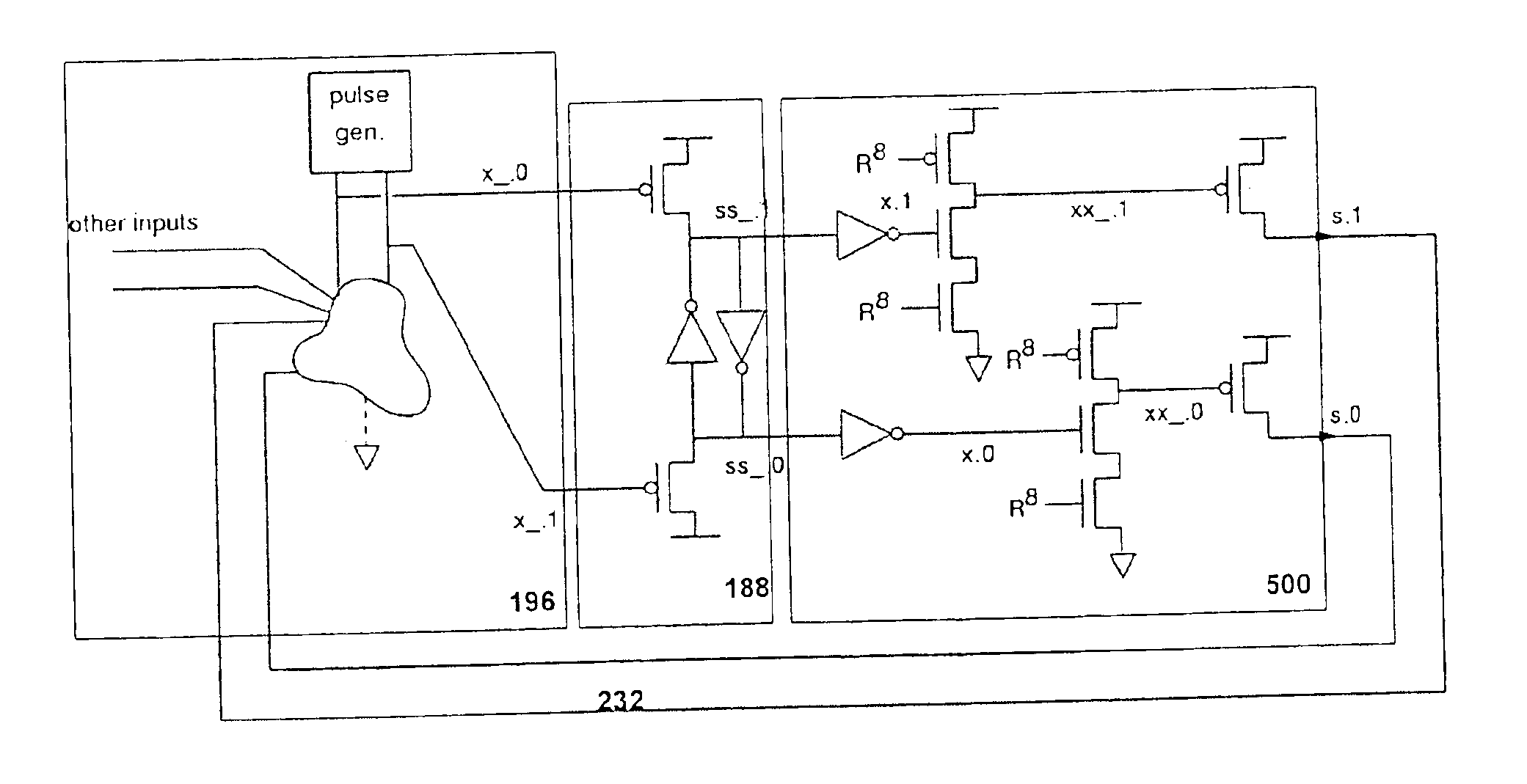
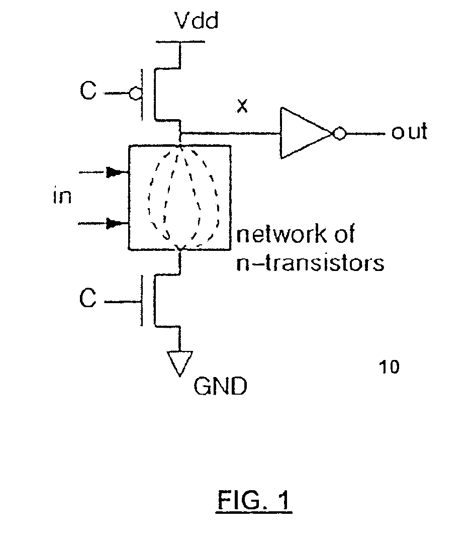
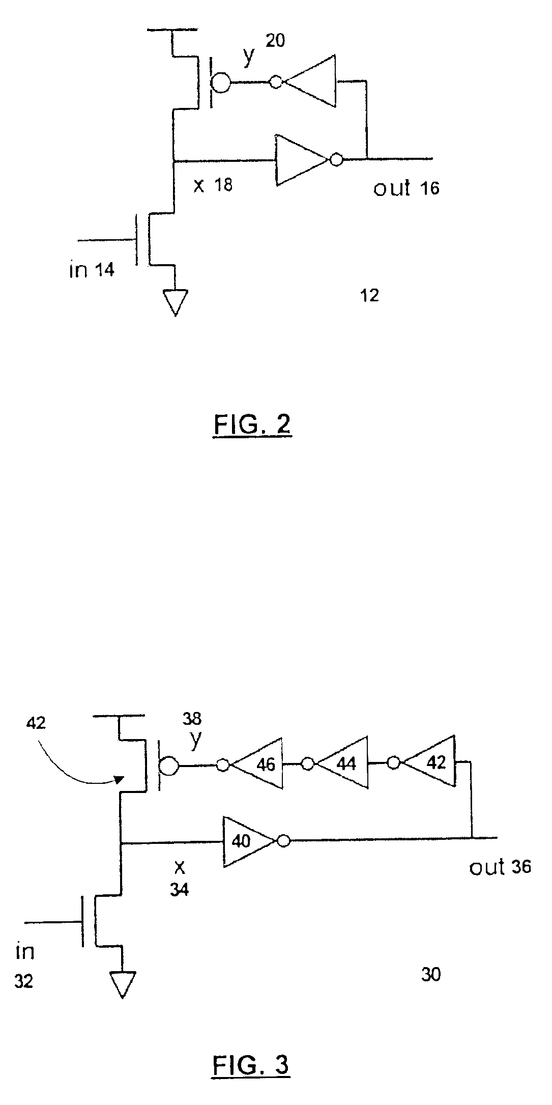
[0024]The present invention is a design style that allows making use of limited amounts of timing information, i.e., limited use of timing assumptions, without destroying the most important, system-simplifying property of QDI design, namely that of the data's carrying its own timing information. The present invention does this by replacing two of the four-phase (return-to-zero) handshakes in a QDI circuit with pulses, thus breaking the timing dependencies that are the source of the performance problems of QDI circuits. One object of the present invention is that of improving the performance of modular asynchronous systems so much that it becomes possible to use asynchronous techniques for implementing large systems that perform well, yet are easy to design.
[0025]The APL scheme of the present invention takes a simple approach: we use a single-track external handshake, and we minimize the number of timing assumptions at the interfaces between processes; internally, in contrast, we design the circuits so that they generate predictably timed internal pulses. This is a separation of concerns: most of the variable parts of an APL circuit (i.e., those parts that vary depending on what CHP is being implemented) are arranged so that their delays do not matter much for the correct operation of the circuit; conversely, the pulse generator, whose internal delays do matter for the correct operation of the circuit, does on the other hand not vary much.
[0026]This is a great benefit from the invariability of the pulse length: since the pulse length varies so little (this is a different way of saying that the pulse repeater has a high length-gain), we commit only a minor infraction if we assume that the length is constant. The simplifying power of this assumption can hardly be overstated: once we have assumed that the pulse length is given, we need only verify that the circuitry generating the pulse and the circuitry latching the pulse work properly given that pulse length, and—this is the important part—we need not consider the effects of the inputs and outputs on the pulse length. This means that we can verify our timing properties locally. In effect, we have reduced a problem consisting of verifying the properties of the solution to a system of N coupled nonlinear equations into one involving N uncoupled nonlinear equations: we have gone from a task that seems insurmountable to one that is (in theory at least) easy.
[0029]An object of the present invention is to improve the ease of design in circuits. In terms of ease of design, STAPL circuits are shown to be as easy to design as their QDI counterparts. STAPL circuits are more sensitive to sizing. It is not clear how important this is for the designer, since QDI sizing must also be verified before fabrication.
[0030]Another object of the present invention is improved circuit performance. In terms of speed, STAPL circuits are undoubtedly faster than QDI circuits. An embodiment of the present invention is a microprocessor, called the SPAM processor, which demonstrates the gain in performance that can be achieved by using STAPL circuits. The embodiment shows that something as large as a microprocessor can be designed with circuits that all run at 10 transitions per cycle, whereas it would be very difficult to do so in less than 18 with only QDI circuits. The reason for the difference is that STAPL circuits remove many waits that are necessary for maintaining QDI protocols and replace them with timing assumptions. Furthermore, STAPL circuits load their inputs less than do QDI circuits, because they generally do not need the completion circuitry that is needed in QDI circuits. The SPAM processor parts that we have simulated run three times as fast as similar parts from the MiniMIPS, a well-known prior art microprocessor.
[0032]Other advantages of STAPL circuits include a simplified solution to the charge-sharing problem and less loading from p-transistors (no input-completion circuitry in most cases, and even when it is present, it has no p-transistors).

Problems solved by technology

So when we imagine and program a VLSI system, we do not allow c and λ to constrain our imagination or to damp our enthusiasm.
Poor performance is usually unacceptable for a VLSI system.
If we should try this with real horses, the harness would act much as the clock does in a synchronous system and render the exercise pointless.
If it is not finished by then, we say that the system is wrong and throw it on the trash heap.
In contrast, the chief difficulty in asynchronous design is knowing when a specific computation is done.
If the delay is too short, the system will not work; if too long, then it will work slowly.
Especially if computation times are data-dependent, the matched delay can easily become a designer's nightmare.
There is one difficulty with QDI design: the requirement that the circuits work properly even if all operator delays were to vary unboundedly is a difficult one to satisfy; our satisfying it involves inserting much circuitry whose only purpose is checking for the occurrences of transitions that we may know would in any case take place.
We should say that QDI systems must still be designed “within reason”: it is possible to make things not work by designing them very poorly; likewise, it still takes considerable work and skill to achieve good performance.

Method used


Image

  • Method and apparatus for an asynchronous pulse logic circuit
  • Method and apparatus for an asynchronous pulse logic circuit
  • Method and apparatus for an asynchronous pulse logic circuit

Examples


Embodiment Construction

[0083]The present invention is an asynchronous pulse logic circuit and methods of designing such a circuit. Embodiments of the present invention comprise of a family of circuit design called the single-track-handshake-asynchronous-pulse-logic (STAPL) circuit. In the following description, numerous specific details are set forth to provide a more thorough description of embodiments of the invention. It is apparent, however, to one skilled in the art, that the invention may be practiced without these specific details. In other instances, well known features have not been described in detail so as not to obscure the invention.

[0084]The present invention aims at establishing a new target for hardware designers. Embodiments are circuits designed according to an asynchronous, pulsed-logic design-style that depends on timing assumptions for working properly, which quasi delay-insensitive (QDI) circuits do not.

[0085]To describe the present invention, we shall use much of the same terminolog...


PUM


Abstract

The present invention is a class of circuits named asynchronous pulse logic (APL) circuit and designing methods for such circuits. APL replaces two of the four-phase handshakes in QDI circuits with pulses, thus breaking the timing dependencies that cause performance problems in QDI circuits. Since the pulse length in APL varies so little, it can be assumed constant. This assumption frees designers from needing to consider the effects of the inputs and outputs on the pulse length, which means timing properties can be verified locally. One embodiment of the present invention is a class of circuit design called the single-track-handshake-asynchronous-pulse-logic (STAPL), which serves as a new target for the compilation of CHP (Communication Hardware Process) programs. In one embodiment, a five-stage pulse generator is used to create a 10 transition count cycle circuit. Advantages of STAPL include a simplified solution to the charge-sharing problem and less loading from p-transistors.

Description

[0001]This application is a divisional application of U.S. patent application Ser. No. 10 / 269,255, filed Oct. 11, 2002, now U.S. Pat. No. 6,732,336, which claims priority to U.S. Provisional Patent Application titled “Asynchronous Pulse Logic”, No. 60 / 328,647, filed on Oct. 11, 2001, and is hereby fully incorporated by reference.[0002]The invention was made by an agency of the United States Government or under a contract with an agency of the United States Government. The name of the U.S. Government agency is DARPA and the Government contract numbers DAAH 04-94-G-0274 and F29601-00K-0184.[0003]Portions of the disclosure of this patent document contain material that is subject to copyright protection. The copyright owner has no objection to the facsimile reproduction by anyone of the patent document or the patent disclosure as it appears in the Patent and Trademark Office file or records, but otherwise reserves all copyright rights whatsoever.BACKGROUND OF THE INVENTION[0004]1. Field...

Claims


Application Information

Patent Timeline
Patent Type & Authority Patents(United States)
IPC IPC(8): G06F17/50H03K19/00H03K19/01G06F7/50G06F9/38H03K19/096
CPCG06F7/5055G06F9/3869G06F17/5045G06F17/5059H03K19/0966G06F30/30G06F30/35
Inventor NYSTROM, MIKAMARTIN, ALAIN J.
Owner CALIFORNIA INST OF TECH
Why Eureka
Try Eureka