
Tunable, multi-port optical add-drop multiplexer

a multi-port, multi-port technology, applied in the field of optical communication, can solve the problems of high through loss of channels, inability to add and drop channels at the same time, and achieve the effect of low loss

Inactive Publication Date: 2005-09-27
LUCENT TECH INC
View PDF4 Cites 20 Cited by
  • Summary
  • Abstract
  • Description
  • Claims
  • Application Information

AI Technical Summary

Benefits of technology

[0011]The present invention realizes a tunable (reconfigurable) OADM that provides multiple drop ports and multiple add ports by which desired channels can be removed from, or added to, a composite optical signal. The channels added to and dropped from the optical signal can be individual channels (with a single wavelength per channel) and therefore enabled for direct connection to fixed (or tunable) optical transmitters and optical receivers, respectively. Alternatively, the channels added to and dropped from the optical signal can themselves be multiplexed, enabling more advanced features. The OADM of the present invention provides a low loss architecture for all the optical signals that traverse through the device, as required for transparent optical networks.

Problems solved by technology

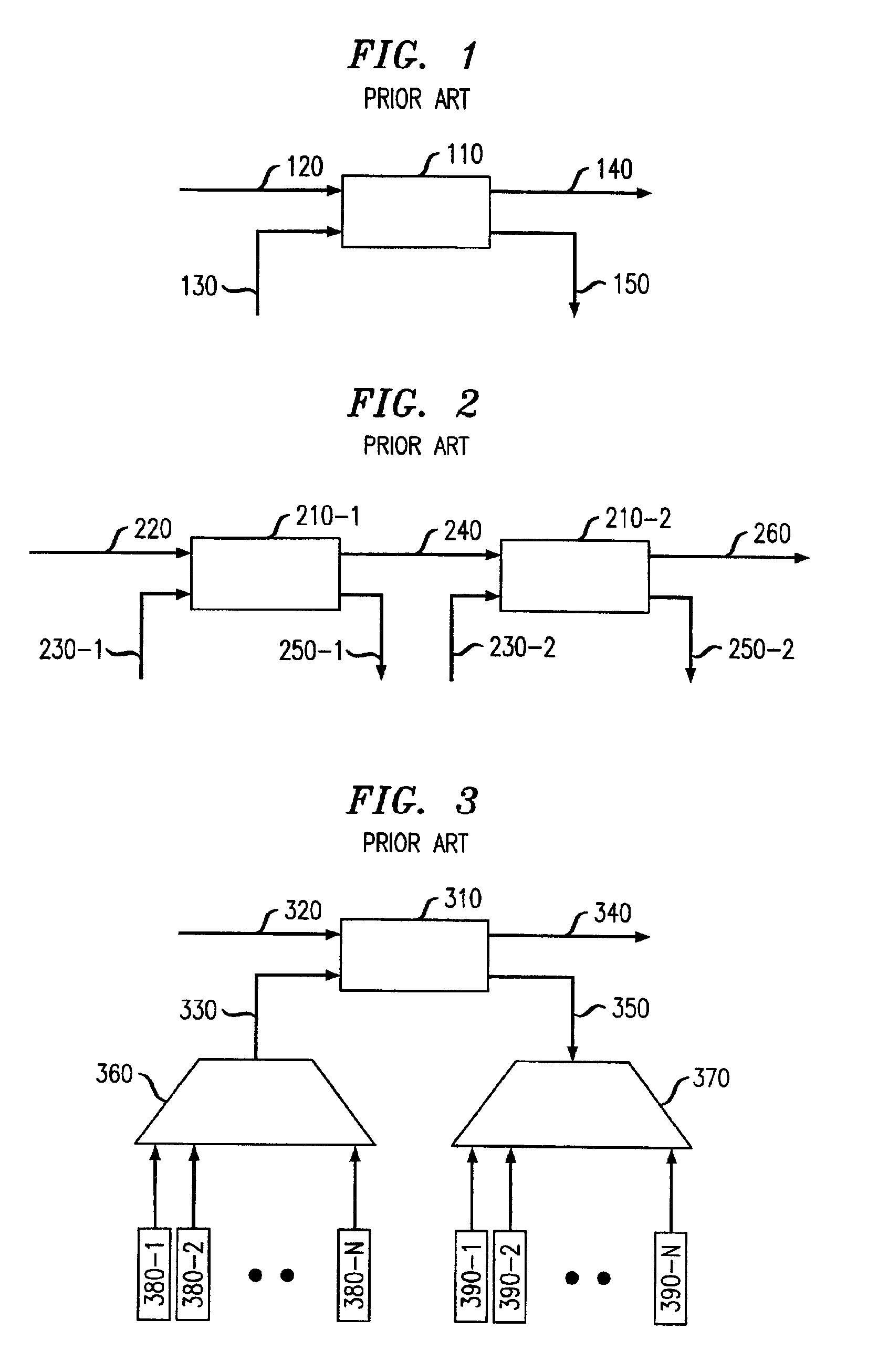
The cascading solution, however, suffers from a high through loss for the channels that have to pass all the OADMs in the cascade from the communication system input 220 to the output 260.
However, in a dynamic optical communication system, the added and dropped channels can change over time, according to demand.
This is a very expensive solution, as only a subset of channels will typically be used at any given time, while the others remain idle.
Tunable transmitters and receivers cannot be used with the multiplexers and demultiplexers, due to the fixed channel assignment between the input and output ports of such devices.
Passive combining and splitting can be used, but the power budget for that solution is impracticable.

Method used


Image

  • Tunable, multi-port optical add-drop multiplexer
  • Tunable, multi-port optical add-drop multiplexer
  • Tunable, multi-port optical add-drop multiplexer

Examples


Embodiment Construction

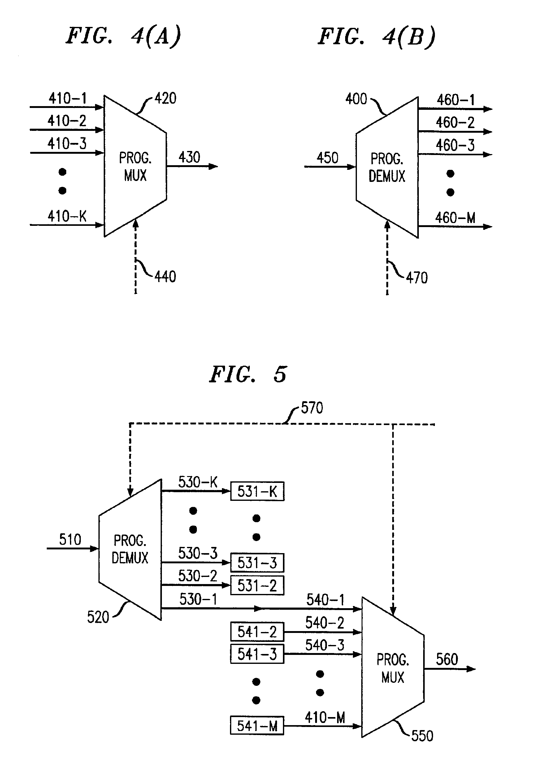
[0023]The present invention describes new architectures for implementing an OADM that advantageously makes use of the programmable optical multiplexer / demultiplexer described in applicant's co-pending application identified above. For the purposes of completeness, the functionality of that element is described in connection with FIGS. 4(a) and 4(b) herein. As illustrated in FIG. 4(a), a programmable optical multiplexer 420 has K input ports 410-1 through 410-K and a single output port 430. Each of the input ports can receive an optical signal containing one or more optical channels from the set of λ-1 through λ-N, provided the channels of each input port are different. The optical signals are combined in the multiplexer, and emerge as a composite signal at output port 430 containing all the optical channels λ-1 through λ-N. Operationally, multiplexer 420 establishes a unique pathway for each optical channel between any one of the input ports 410-1 through410-K and the output port 43...


PUM


Abstract

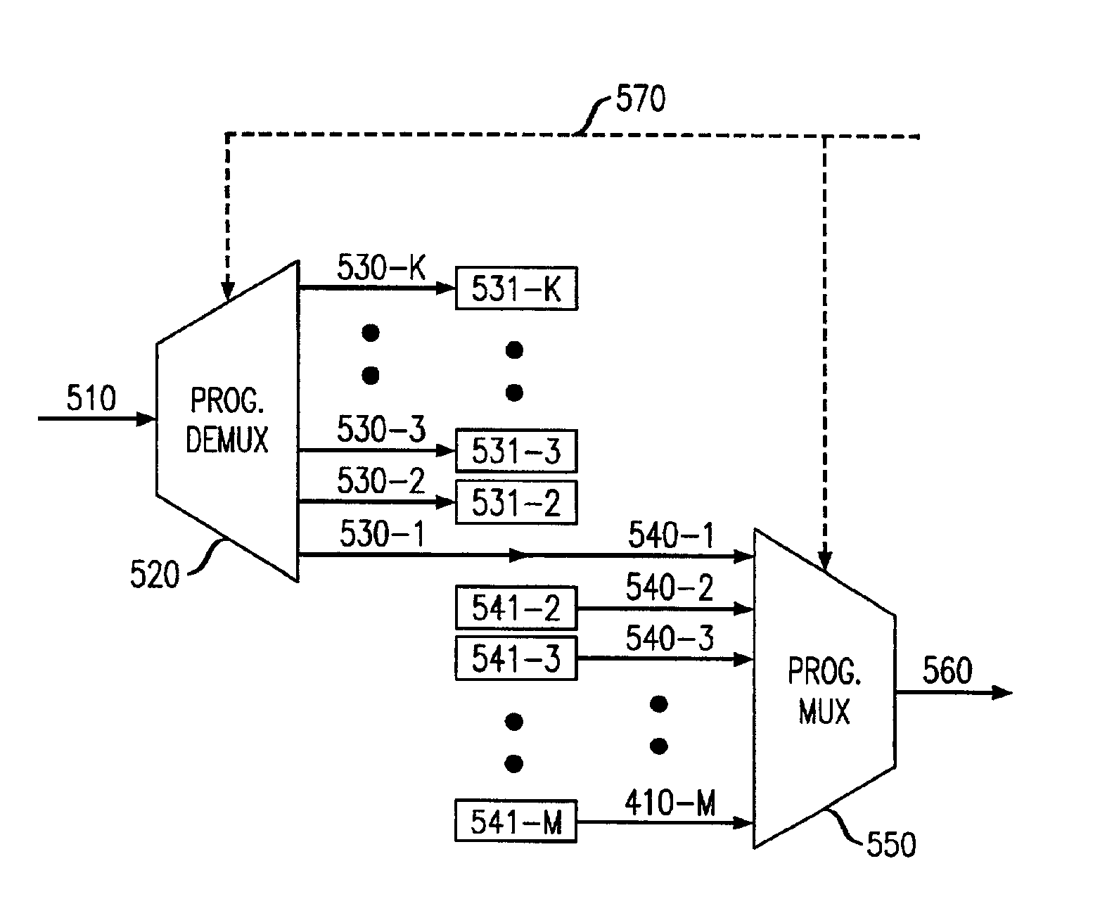
A tunable (reconfigurable) OADM provides multiple drop ports and multiple add ports by which desired channels can be removed from, or added to, a composite optical signal. In one embodiment, a programmable demultiplexer is arranged to receive an input signal containing components at x different wavelengths from an optical input port, and distribute the input signal components among K output ports. K−1 of the output ports are the “drop” ports of the OADM, and cumulatively contain w different wavelengths. The remaining port, which is the “through port” that carries the z wavelengths not dropped from the original input signal, is connected to the first port of an M port programmable multiplexer having M−1 other input ports. The remaining M−1 ports are the “add” ports of the OADM, which cumulatively receive v different wavelengths to be added by the OADM.

Description

CROSS-REFERENCE TO RELATED APPLICATION[0001]This application claims priority of Provisional Application Ser. No. 60 / 300,272 which was filed on Jun. 22, 2001.TECHNICAL FIELD[0002]The present invention relates to optical communications, and more particularly to an arrangement for a tunable, multi-port optical add-drop multiplexer (OADM) that can add optical channels to, and extract optical channels from, an optical signal in a wavelength division multiplexing (WDM) system.BACKGROUND OF THE INVENTION[0003]The transmission capacity of fiber-optic communication systems has increased significantly by use of the wavelength division multiplexing (WDM) technique. In a WDM system, multiple channels, where each channel is differentiated by using a different wavelength of light, each carry modulated optical signals in a single optical fiber between transmitter and receiver nodes. In a typical optical communication system, it is desirable to have a few access nodes along the fiber path between t...

Claims


Application Information

Patent Timeline
Patent Type & Authority Patents(United States)
IPC IPC(8): H04J14/02H04Q11/00
CPCH04J14/0209H04J14/021H04J14/0212H04J14/0213H04Q11/0005H04J14/0206H04J14/0216H04Q2011/0016
Inventor MAROM, DAN MARK
Owner LUCENT TECH INC
Learn More