Plant controller for frequency-shaping response-designating control having a filtering function

a technology of frequency-shaping response and plant controller, which is applied in the direction of electrical control, automatic control, instruments, etc., can solve the problems of high-frequency vibration, difficult to keep control accuracy, and difficulty in causing actual rotational speed to converge to the target rotational speed, etc., to achieve high accuracy, easy to pass, and implement with ease

Inactive Publication Date: 2005-09-27
HONDA MOTOR CO LTD
View PDF7 Cites 17 Cited by
  • Summary
  • Abstract
  • Description
  • Claims
  • Application Information

AI Technical Summary

Benefits of technology

[0030]According to another embodiment, the filter is implemented with a computer program. The internal variable of the filter can be easily passed to the control algorithm. The frequency-shaping response-designating control may be implemented with a computer program. Thus, the control is implemented with ease and high accuracy.
[0031]According to another embodiment, the frequency-shaping response-designating control algorithm is performed when the engine is in an idling state. Thus, the tracking capability of the plant in the idling state is improved. The response, stability and robustness of the idling rotational speed control are improved.
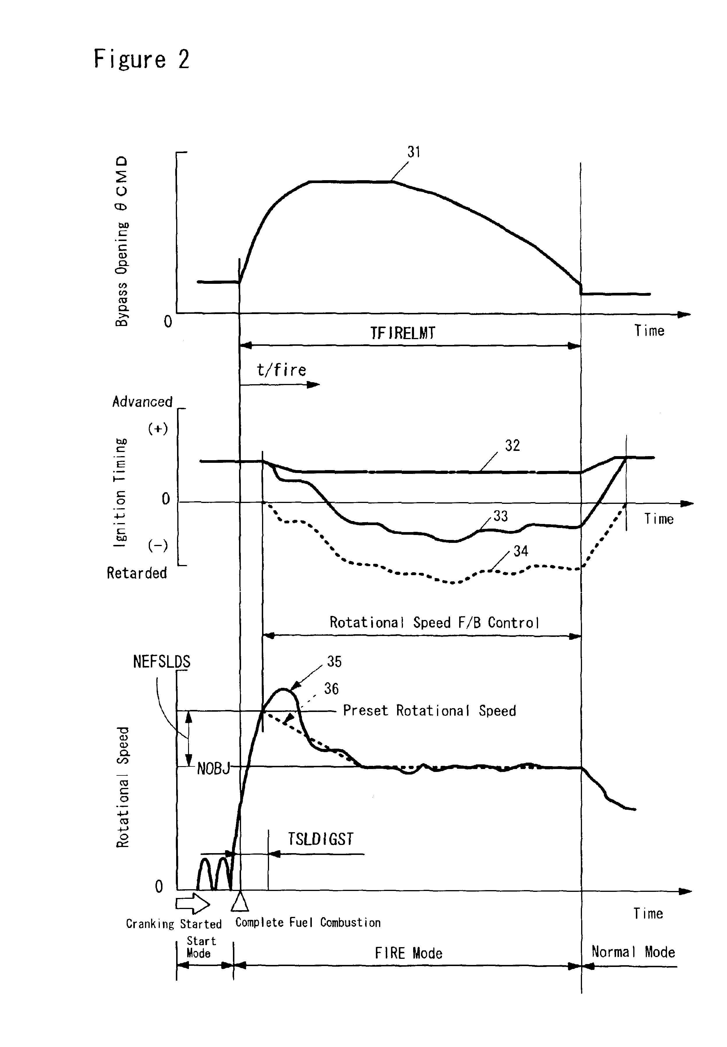
[0032]According to another embodiment, the frequency-shaping response-designating control algorithm is performed in warming-up control for an exhaust system. In the warming-up control, the amount of intake air introduced into the engine is increased so as to quickly activate a catalyst converter at the start of the engine. Thus, the catalyst converter is quickly activated while the response, stability and robustness of the control are maintained at high level.

Problems solved by technology

Therefore, it is difficult to cause the actual rotational speed to converge to the target rotational speed.
It is also difficult to keep the accuracy of the control at high level.
The idling rotational speed control by the above sliding mode control may cause high-frequency vibrations.
Such frequency components may cause vibrations to seats, display, etc. inside the vehicle, making vehicle occupants uncomfortable.
However, depending on operating conditions of the engine, it may be difficult to hold the switching function at zero.
If the switching function cannot be held at zero, the entire control system may become unstable.

Method used


Image

  • Plant controller for frequency-shaping response-designating control having a filtering function
  • Plant controller for frequency-shaping response-designating control having a filtering function
  • Plant controller for frequency-shaping response-designating control having a filtering function

Examples


first embodiment

of Controller in Rotational Speed Control

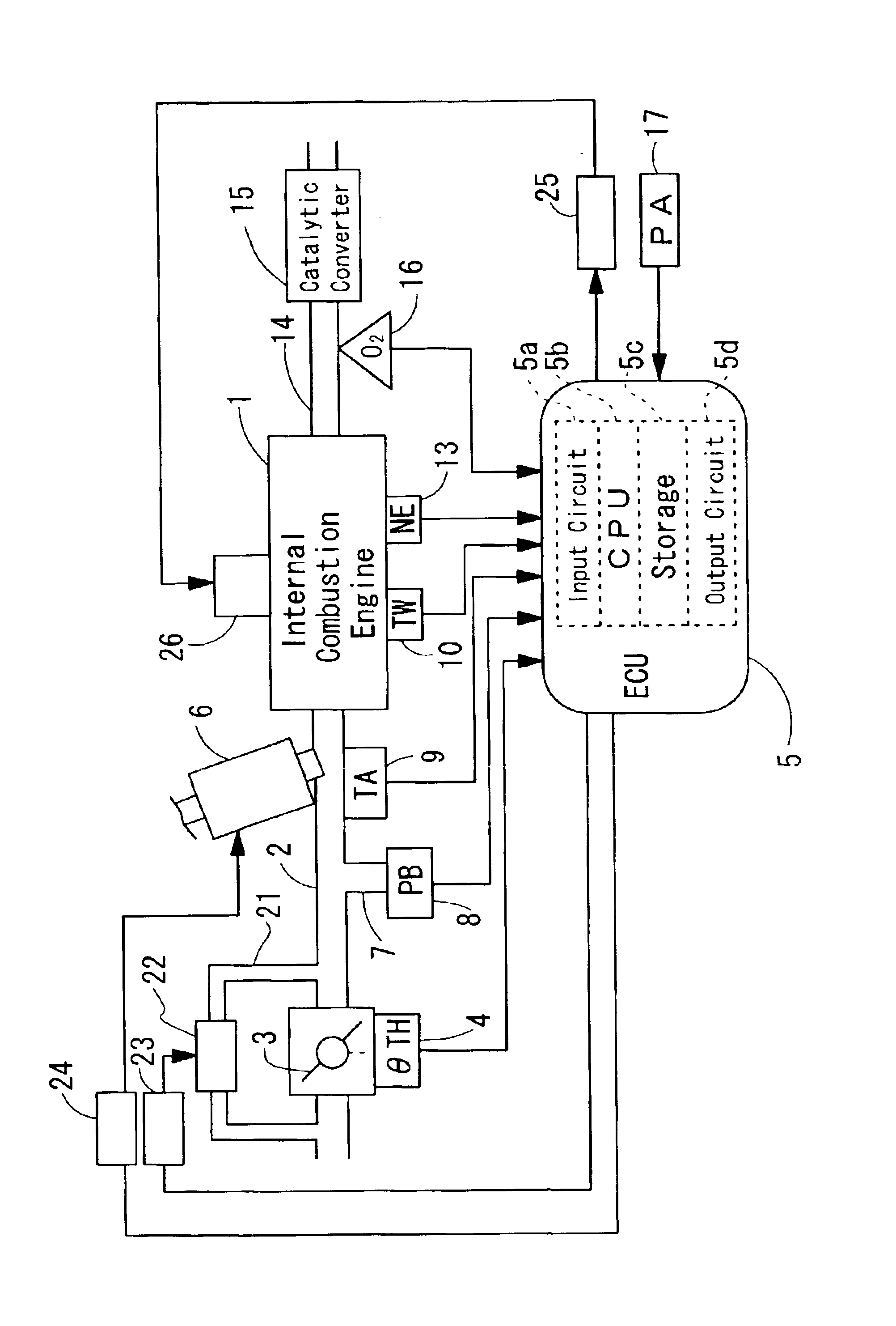
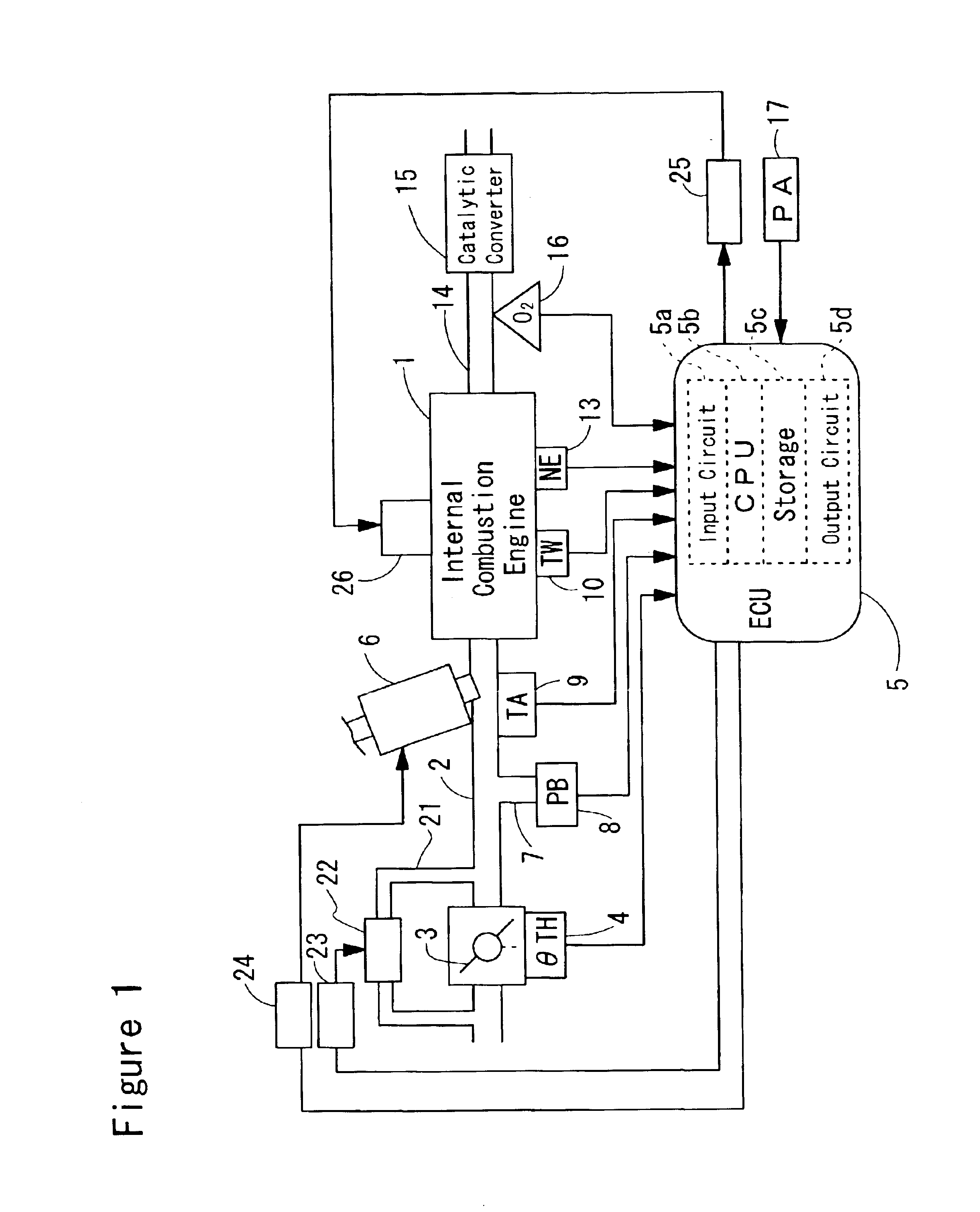
[0129]FIG. 10 is a detailed block diagram for the controller 71 shown in FIG. 8 in accordance with a first embodiment of the invention. The controller 71 further comprises a low-pass filter 81 and a frequency-shaping sliding mode controller (hereinafter referred to as a “sliding mode controller”) 82. The error En between the actual rotational speed Ne detected by the rotational sensor 13 and the target rotational speed ne / fire is passed to the low-pass filter 81. The low-pass filter 81 removes higher frequency components from the rotational speed error En to generate a signal NElow.

[0130]The sliding mode controller 82 receives the rotational speed error En, a state variable (which is also referred to as an internal variable) Z of the low-pass filter 81, and the signal NElow generated by the low-pass filter 81. The sliding mode controller 82 performs sliding mode control to determine the ignition timing corrective quantity DIG so that the rota...

second embodiment

of Rotational Speed Control

[0164]FIG. 15 shows a detailed block diagram of the controller 71 (FIG. 8) in accordance with a second embodiment of the invention. As seen compared to FIG. 10, the second embodiment is different from the first embodiment in that a linear transformation type of frequency-shaping sliding-mode controller 182 (hereinafter referred to as a linear sliding mode controller) is provided. The linear sliding mode controller 182 uses linear independent state variables as the control input to perform response-designating control. Such response-designating control is called linear transformation type of frequency-shaping response-designating control. In the embodiment, the control is implemented with a linear transformation type of frequency-shaping sliding-mode control.

[0165]A low-pass filter 81 may be the same as that of FIG. 10. A state equation and an output equation for the low-pass filter 81 can be expressed by the above equations (14) and (15), respectively. The...


PUM


Abstract

A plant controller controls a plant modeled in a discrete-time system. The controller uses a frequency-shaping response-designating control algorithm having a filtering function to cause a difference between output of the plant and a target value to converge. Thus, the plant is robustly controlled without causing undesired frequency components. When the plant is an engine, the engine is modeled using a ignition timing corrective quantity as input and a rotational speed as output. The controller performs the frequency-shaping response-designating control algorithm to determine the ignition timing corrective quantity. The frequency-shaping response-designating control may be frequency-shaping sliding-mode control. In one embodiment, the control input into the plant may includes a corrective term for stabilizing an internal variable of the filter, a corrective term for stabilizing the difference between the output of the plant and the target value and a corrective term that varies depending on a switching function.

Description

TECHNICAL FIELD[0001]The invention relates to a plant controller for performing frequency-shaping response-designating control having a filtering function, and more specifically relates to a controller for robustly controlling rotational speed of an internal combustion engine through frequency-shaping response-designating control having a filtering function.BACKGROUND OF THE INVENTION[0002]When the engine is cold-started, a catalytic converter provided in an exhaust system of the engine is cold. Exhaust gases are emitted through the inactive catalytic converter. In order to avoid such a situation, rapid catalyst warming-up control for rapidly activating the catalytic converter at the start of the engine is proposed.[0003]According to an example of the rapid catalyst warming-up control, the amount of intake air introduced into the engine is increased when the engine is in an idling state immediately after the start of the engine. The rotational speed of the engine is increased, there...

Claims


Application Information

Patent Timeline
Patent Type & Authority Patents(United States)
IPC IPC(8): G05B13/04G05B13/02G05B21/02G05B21/00F01N3/20F02P5/15F02D41/04F02D45/00
CPCG05B13/021G05B13/047G05B21/02
Inventor ISHIKAWA, YOSUKEYASUI, YUJI
Owner HONDA MOTOR CO LTD
Why Eureka
Try Eureka