Failure diagnosis apparatus for evaporative fuel processing system

a technology of evaporative fuel and failure diagnosis, which is applied in the direction of fluid tightness measurement, combustion air/fuel air treatment, instruments, etc., can solve the problems of increasing manufacturing cost, reducing the load current value of the motor pump, and evaporating fuel in the evaporative fuel processing system. , to achieve the effect of rapid leak detection and simple configuration

Inactive Publication Date: 2005-09-27
HONDA MOTOR CO LTD
View PDF3 Cites 32 Cited by
  • Summary
  • Abstract
  • Description
  • Claims
  • Application Information

AI Technical Summary

Benefits of technology

[0006]It is an object of the present invention to provide a failure diagnosis apparatus which can rapidly perform leak determination of an evaporative fuel processing system with a comparatively simple configuration after stoppage of the internal combustion engine.

Problems solved by technology

Specifically, if there is a leak in the evaporative fuel processing system, the load current value of the motor pump decreases.
The conventional apparatus described above requires a motor pump for air-pressurization and raises a problem that the configuration of the apparatus becomes complicated, thereby increasing manufacturing cost.
The conventional apparatus further raises a problem that, if there is a leak, evaporative fuel in the evaporative fuel processing system is emitted into the atmosphere by the air-pressurization.

Method used


Image

  • Failure diagnosis apparatus for evaporative fuel processing system
  • Failure diagnosis apparatus for evaporative fuel processing system
  • Failure diagnosis apparatus for evaporative fuel processing system

Examples


first embodiment

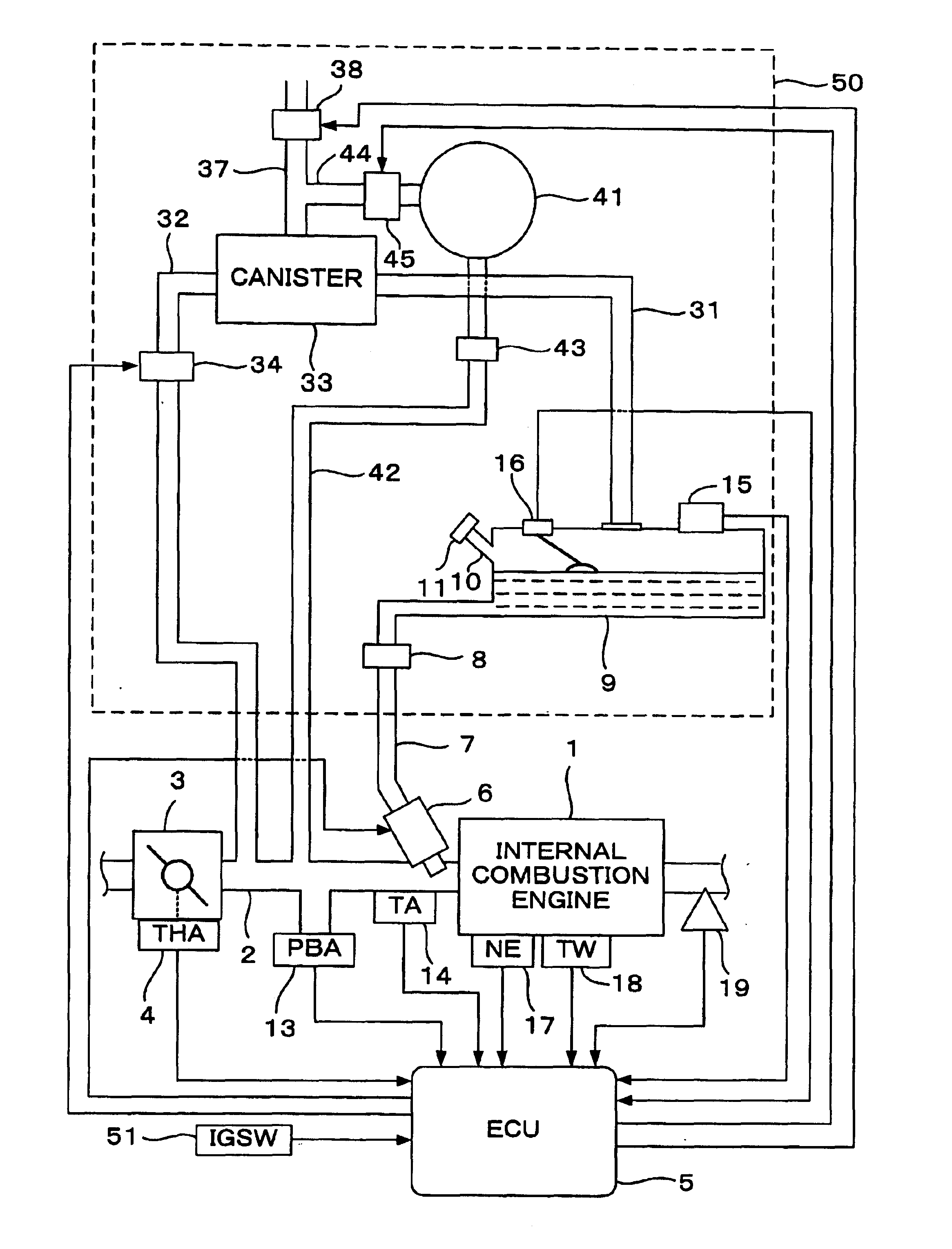
[0032]FIG. 1 is a schematic diagram of an evaporative fuel processing system and a control system of an internal combustion engine according to a first embodiment of the present invention. Referring to FIG. 1, an internal combustion engine (hereinafter referred to as “engine”) 1 having, for example, four cylinders has an intake pipe 2 provided with a throttle valve 3. A throttle valve opening (THA) sensor 4 is connected to the throttle valve 3 and supplies an electric signal corresponding to an opening of the throttle valve 3 to an electronic control unit (hereinafter referred to as ECU) 5.

[0033]A portion of the intake pipe 2 between the engine 1 and the throttle valve 3 is provided with a plurality of fuel injection valves 6, respectively corresponding to the plural cylinders of the engine 1 at positions slightly upstream of the respective intake valves (not shown). Each fuel injection valve 6 is connected through a fuel supply pipe 7 to a fuel tank 9. The fuel supply pipe 7 is pro...

second embodiment

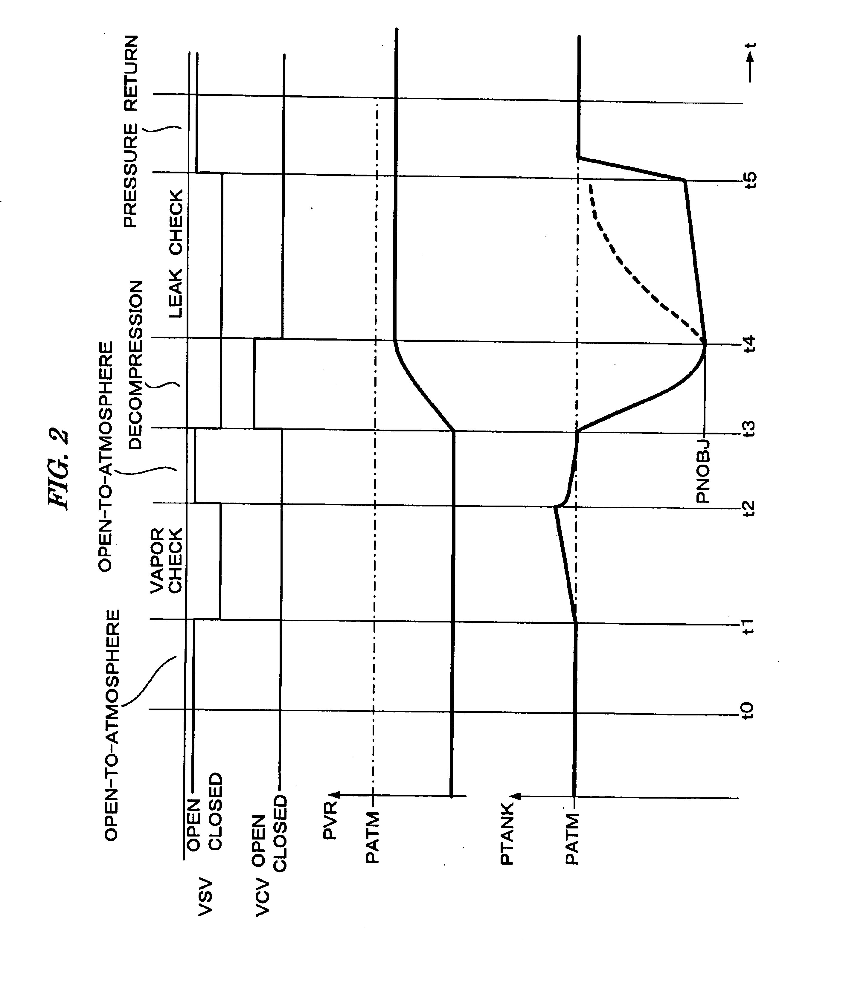
[0081]In the present embodiment, the determination of whether there is a leak is performed focusing on the change amount (hereinafter referred to as “pressure change amount”) DP of the tank pressure PTANK per predetermined time period (for example, 1 second) in the leak check mode process. As shown in FIG. 2, when there is no leak, the tank pressure PTANK in the leak check mode rises substantially linearly with a small inclination (rate of increase). Therefore, the pressure change amount DP takes a value which is low and substantially constant.

[0082]In contrast, when there is a leak, changes in the tank pressure PTANK show a tendency that the tank pressure PTANK initially increases with a comparatively great inclination and the inclination gradually decreases. Accordingly, the pressure change amount DP decreases gradually.

[0083]FIGS. 10A and 10B are time charts showing changes in actually measured values of the pressure change amount DP in the leak check mode. FIG. 10A corresponds t...


PUM


Abstract

A failure diagnosis apparatus for diagnosing a failure of an evaporative fuel processing system. The system includes a fuel tank, a canister having adsorbent for adsorbing evaporative fuel generated in the fuel tank, an air passage connected to the canister and communicating the canister with the atmosphere, a first passage for connecting the canister and the fuel tank, a second passage for connecting the canister and an intake system of an internal combustion engine, a vent shut valve for opening and closing the air passage, and a purge control valve provided in the second passage. A pressure in the evaporative fuel processing system is detected. Negative pressure in the intake system is reserved in a negative pressure reservoir during operation of the engine. The purge control valve and the vent shut valve are closed to introduce the reserved negative pressure into the evaporative fuel processing system, when stoppage of the engine is detected. It is determined whether or not there is a leak in the evaporative fuel processing system, based on the pressure detected during a predetermined determination period after introduction of the negative pressure.

Description

BACKGROUND OF THE INVENTION[0001]1. Field of the Invention[0002]This invention relates to a failure diagnosis apparatus for diagnosing a failure of an evaporative fuel processing system which temporarily stores evaporative fuel generated in a fuel tank and supplies the stored evaporative fuel to an internal combustion engine.[0003]2. Description of the Related Art[0004]A failure diagnosis apparatus for determining whether or not there is a leak in an evaporative fuel processing system after stoppage of an internal combustion engine is disclosed, for example, in Japanese Patent Laid-Open No. 2002-357164. According to this apparatus, air is pressurized by a motor pump and introduced into the evaporative fuel processing system. The determination of whether there is a leak is performed based on a load current value of the motor pump upon air-pressurization. Specifically, if there is a leak in the evaporative fuel processing system, the load current value of the motor pump decreases. The...

Claims


Application Information

Patent Timeline
Patent Type & Authority Patents(United States)
IPC IPC(8): G01M3/02F02M25/08
CPCG01M3/025
Inventor YAMAGUCHI, TAKASHIKUBO, SATORUSHIKAMA, MAHITO
Owner HONDA MOTOR CO LTD
Why Eureka
Try Eureka