Optical ferrule-less connector

a technology of optical connectors and ferrules, applied in the field of optical connectors, can solve the problems of reducing yield, reworking and waste, and high cost of polishing with such stringent requirements

Inactive Publication Date: 2005-10-04
TYCO ELECTRONICS NETHERLAND BV
View PDF1 Cites 50 Cited by
  • Summary
  • Abstract
  • Description
  • Claims
  • Application Information

AI Technical Summary

Benefits of technology

[0018]Yet another fiber control feature of the present invention is axially aligning the fiber with the V-grooves. Specifically, the connector of the present invention preferably aligns the fiber with the V-groove such that the fiber does not assert a buckling force on the V-groove. Instead, the b...

Problems solved by technology

Polishing with such stringent requirements tends to be costly and prone to reworking and waste, thereby lowering yields.
The problems associated with polishing the ferrule are exasperated in multi-fiber ferrules which are more complicated to polish.
In single fiber ferrules, this bulk can negatively affect the minimum center line distance between fibers, which is particularly problematic as the need for fiber density increases.
First, most of the disclosed approaches rely on a fiber being fixed to one end of a connector while the free end of fiber is cantilevered.
A cantilevered fiber, however, is very delicate and easily damaged.
Furthermore, the cantilevered portion is “bare fiber” meaning that its protective coating has been stripped, thus rendering the cantilevered fiber even more susceptible to damage.
The applicants have also recognized that the approaches disclosed in Kobayashi et al. do not offer sufficient control over the buckling of the cantilevered end.
The applicants have identified a number of problems associated with this uncontrolled buckling.
First, in multi-fiber assemblies, the buckled fibers are likely to interfere with each other thereby resulting in an uneven pressure at the fiber end face interface.
As is well known, scratches on the end face of a fiber or wave guide drastically diminish its optical performance and ability to optically couple.
The applicants have also identified that another problem with the approaches of Kobayashi et al. is the use of micro holes in the alignment member.
Micro holes tend to be problematic when interfacing a fiber to an optical device such as a laser diode or photo detector.
Furthermore, if dust or other debris is in the hole it will likely force the fiber to one side of the hole ...

Method used


Image

  • Optical ferrule-less connector
  • Optical ferrule-less connector
  • Optical ferrule-less connector

Examples


Embodiment Construction

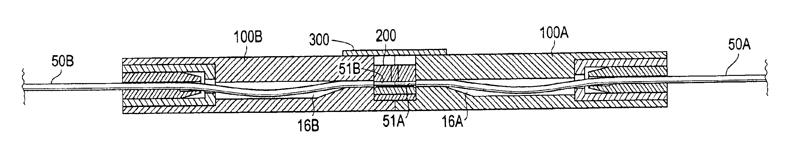
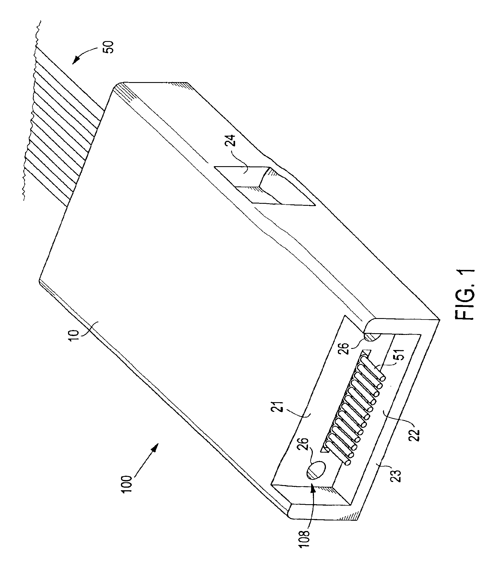
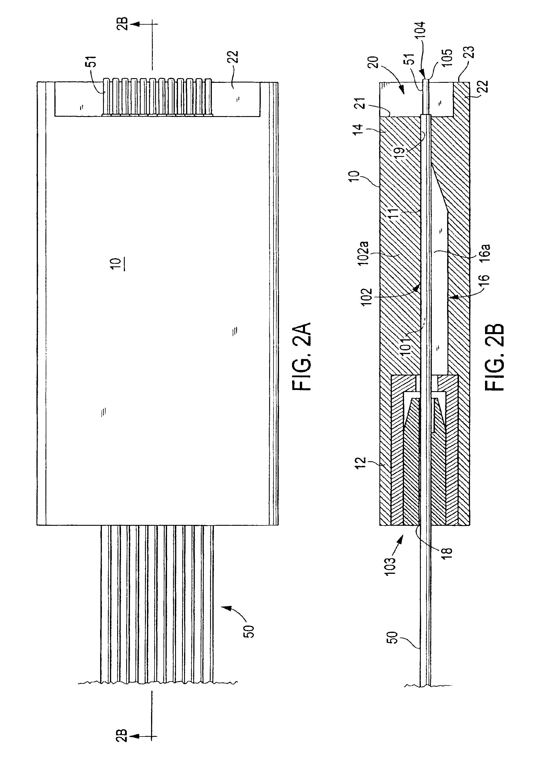
[0028]The present invention provides for an optical ferrule-less connector having enhanced control over the fibers it contains during the mating process to ensure a reliable and repeatable physical contact (“PC”) between the fibers of the connector and the optical pathways of a mating optical structure. The term “optical pathway,” as used herein, refers to any medium for conducting optical signals including the following: a fiber or waveguide; a silica or polymeric structure in a substrate; or a silica or polymeric optical component. The term “mating component” refers to an optical package that contains or comprises the optical pathway. For example, a mating component may be another connector, herein a “mating connector” or it may be an optical device in which the mating optical pathway is an integral component. Examples of optical devices include passive devices, such as, add / drop filters, arrayed wave guide gratings (AWGs), splitters / couplers, and attenuators, and active devices, ...


PUM


Abstract

An optical connector for optically coupling a fiber to an optical pathway of a mating component when in a mated state, the connector comprising: (a) a housing having a front end portion and a back end portion, the housing having at least one passageway extending from the back end portion to the front end portion to accommodate at least one fiber, the housing defining a cavity along a first portion of the passageway such that a fiber in the passageway is deflected into the cavity when the connector is in the mated state; (b) a barrier along a second portion of the passageway, the barrier preventing a fiber from being deflected into the second portion when the connector is in the mated state; (c) a fiber retainer at the back end portion, the fiber retainer adapted to restrict a fiber's backward movement with respect to the housing when in the mated state; and (d) the front end portion being configured to mate with an alignment member such that a fiber in the passageway is received within a passage of the alignment member, the front end having a first end face having an opening through which the passageway extends such that a fiber in the passageway is supported at the back end portion by the fiber retainer and at the front end portion by the end face and is deflected between the front and back end portions during mating.

Description

CROSS REFERENCE TO RELATED APPLICATIONS[0001]This application is a U.S. national stage application based on International Application No. PCT / US01 / 47694, filed Oct. 25, 2001, which claims priority to U.S. Provisional Application Nos. 60 / 242,997, filed Oct. 25, 2000, and 60 / 243,275, filed Oct. 25, 2000.FIELD OF INVENTION[0002]The present invention relates generally to optical connectors, and, more specifically, to ferrule-less optical connectors.BACKGROUND OF INVENTION[0003]Optical fiber connectors are an essential part of substantially all optical fiber communication systems. For instance, such connectors are used to join segments of fiber into longer lengths, to connect fiber to active devices such as radiation sources, detectors and repeaters, and to connect fiber to passive devices such as switches and attenuators. The principal function of an optical fiber connector is to hold a fiber end such that the core of the fiber is axially aligned with the optical pathway of the componen...

Claims


Application Information

Patent Timeline
IPC IPC(8): G02B6/38G02B6/30G02B6/42
CPCG02B6/3809G02B6/3821G02B6/3839G02B6/3873G02B6/3885G02B6/30G02B6/3823G02B6/3825G02B6/3847G02B6/3874G02B6/4249G02B6/4292
Inventor VERGEEST, HENRICUS
Owner TYCO ELECTRONICS NETHERLAND BV
Why Eureka
Try Eureka