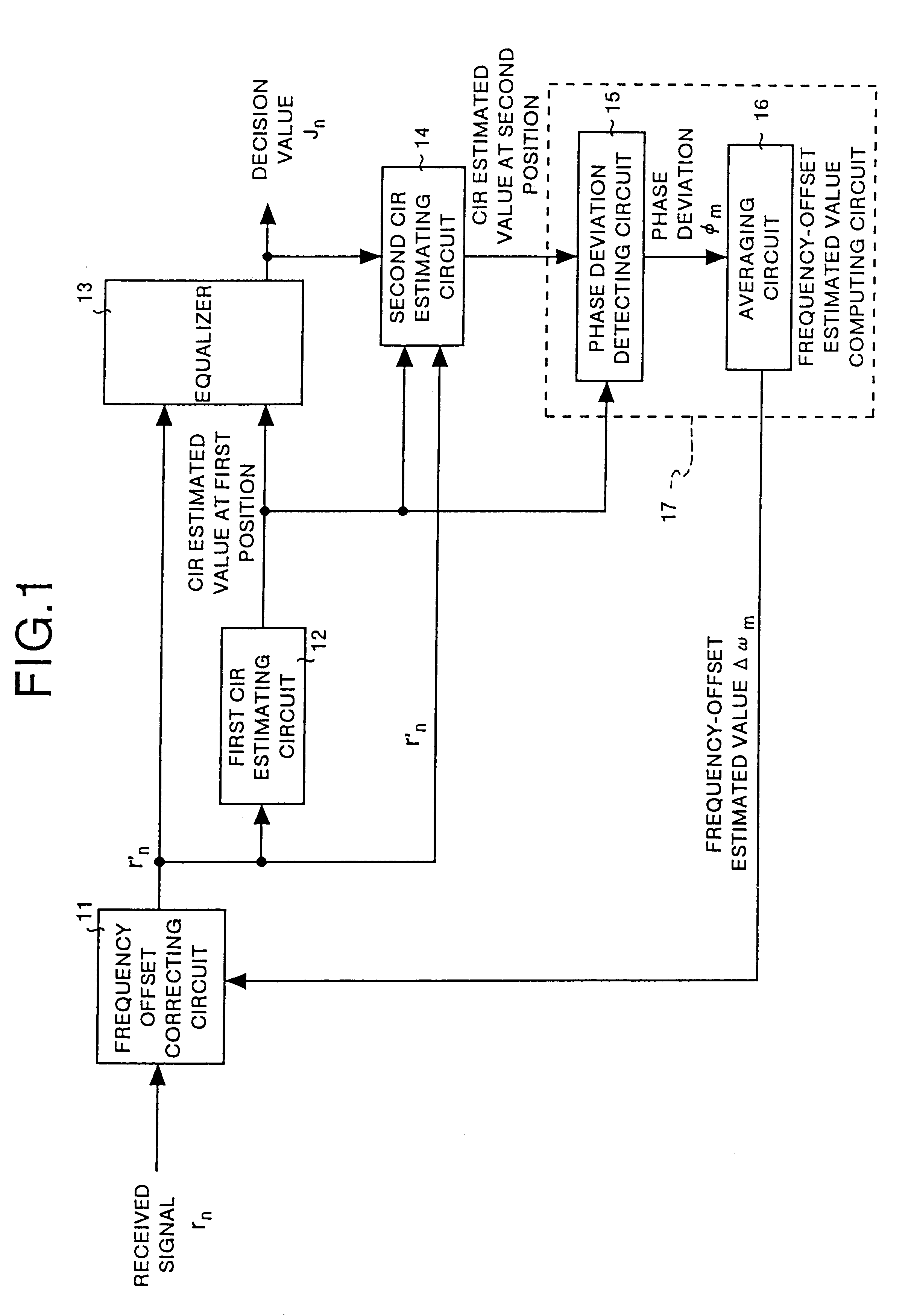
[0029]To achieve the object as described above, the present invention comprises a frequency offset correcting means for receiving a received signal as well as a frequency-offset estimated value and correcting
phase rotation due to frequency offset of the received signal according to the frequency-offset estimated value; a first
channel impulse response estimating means for estimating
channel impulse response at a first position of the corrected received signal according to a known training sequence included in the received signal corrected by the frequency offset correcting means; a determining means for determining the received signal corrected by the frequency offset correcting means according to the channel
impulse response estimated value at the first position thereof estimated by the first channel
impulse response estimating means; a second channel
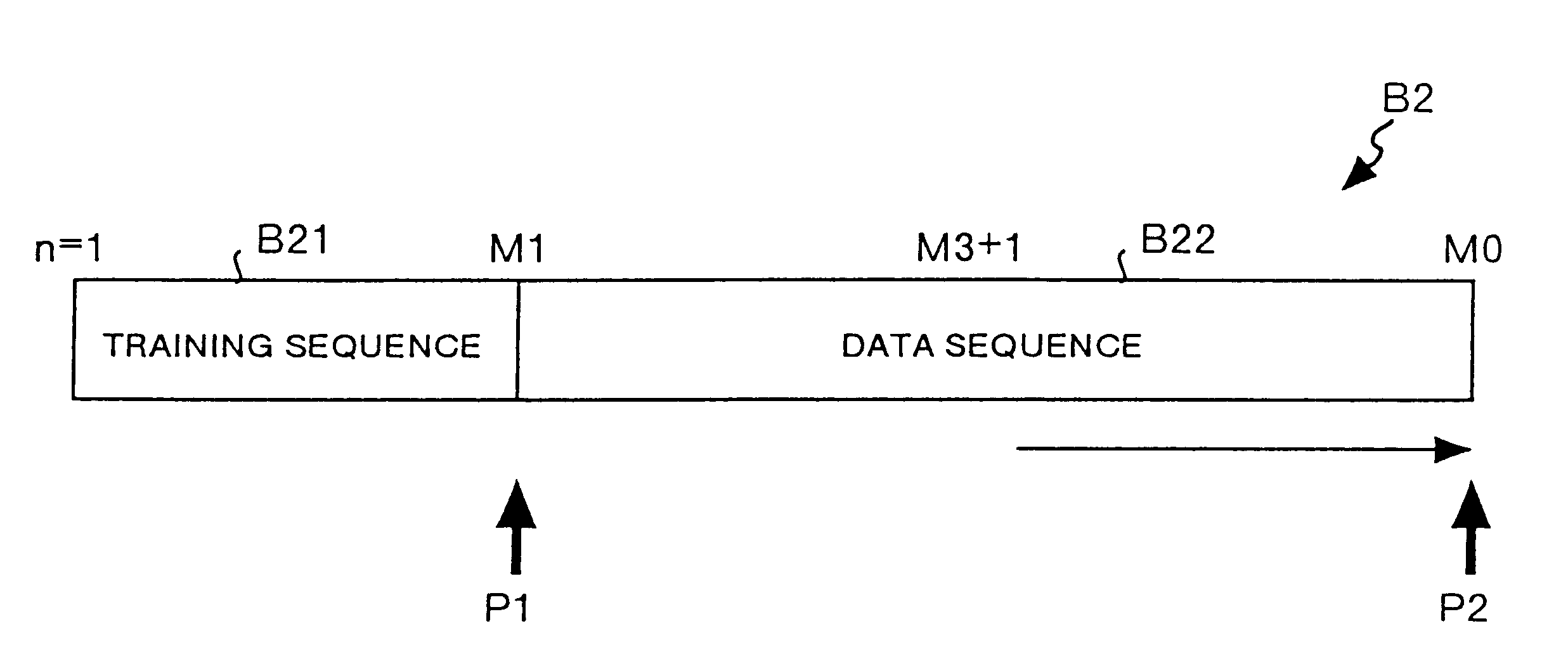
impulse response estimating means for estimating channel impulse response at a second position apart from the first position of the corrected received signal according to the received signal corrected by the frequency offset correcting means, the channel impulse response estimated value at the first position thereof estimated by the first channel impulse response estimating means, and to the value determined by the determining means; and a frequency-offset estimated value computing means for computing a frequency-offset estimated value of the received signal according to the channel impulse response estimated value at the first position thereof estimated by the first channel impulse response estimating means as well as to the channel impulse response estimated value at the second position thereof estimated by the second channel impulse response estimating means, and outputting the computed value to the frequency offset correcting circuit. Therefore, with this invention, different channel-impulse estimated values at the first and second positions are obtained according to the training sequence having been known in the received signal, and a frequency-offset estimated value is computed according to those phase deviations, so that frequency offset of a received signal can be corrected and also data can be determined without using known data such as tail bits other than the training sequence. As a result, tail bits are not needed as a burst structure of a received signal, so that transmission efficiency is improved, and also a
phase deviation can be computed not according to an estimated value (replica) of the received signal computed only with tail bits in a transmission sequence but according to channel impulse response estimated by sufficiently suppressing a
noise element with an appropriate
algorithm (e.g., LMS
algorithm), and for this reason a
phase deviation to be detected does not largely varies with noises, time-varying frequency offset can be compensated with high precision, and data can be determined at a low error rate.
[0030]The another present invention comprises a frequency offset correcting means for receiving a received signal as well as a frequency-offset estimated value and correcting
phase rotation due to frequency offset of the received signal according to the frequency-offset estimated value; a first channel impulse response estimating means for estimating channel impulse response at a first position of the corrected received signal according to a known training sequence included in the received signal corrected by the frequency offset correcting means; a determining means for determining the received signal corrected by the frequency offset correcting means; a second channel impulse response estimating means for estimating channel impulse response at a second position apart from the first position of the corrected received signal by updating the channel impulse response estimated value at the first position according to the received signal corrected by the frequency offset correcting means, the channel impulse response estimated value at the first position thereof estimated by the first channel impulse response estimating means, and to the value determined by the determining means; and a frequency-offset estimated value computing means for computing a frequency-offset estimated value of the received signal according to the channel impulse response estimated value at the first position thereof estimated by the first channel impulse response estimating means as well as to the channel impulse response estimated value at the second position thereof estimated by the second channel impulse response estimating means, and outputting the computed value to the frequency offset correcting circuit; and the determining means determines the received signal corrected by the frequency offset correcting means, at first, according to the channel impulse response estimated value at the first position thereof estimated by the first channel impulse response estimating means, and determines the received signal corrected by the frequency offset correcting means, after the second time and on, according to a value updated from the channel impulse response estimated value at the first position thereof by the second channel impulse response estimating means. For this reason, with this invention, determination of the received signal after the second time and on is made according to values obtained, by successively updating the channel impulse response estimated value at the first position, outputted from the second estimating means, so that, even when the channel impulse response estimated value varies with time, the variation can be followed, and data can be determined at a low error rate.
[0031]The another present invention comprises a first channel impulse response estimating means for estimating channel impulse response at a first position of the received signal according to a known training sequence included in the received signal; a determining means for determining the received signal according to the channel impulse response estimated value at the first position thereof estimated by the first channel impulse response estimating means; a second channel impulse response estimating means for estimating channel impulse response at a second position apart from the first position of the received signal according to the received signal, the channel impulse response estimated value at the first position thereof estimated by the first channel impulse response estimating means, and to the value determined by the determining means; a frequency-offset estimated value computing means for computing a frequency-offset estimated value of the received signal according to the channel impulse response estimated value at the first position thereof estimated by the first channel impulse response estimating means as well as to the channel impulse response estimated value at the second position thereof estimated by the second channel impulse response estimating means; and a
local oscillator correcting means for correcting a frequency from a
local oscillator according to the frequency-offset estimated value computed by the frequency-offset estimated value computing means. Therefore, with this invention, a frequency from the
local oscillator of the receiver is directly controlled in place of correcting frequency offset of the received signal, so that configuration of the circuit can be simplified.
[0032]The another present invention comprises a frequency offset correcting means for receiving a plurality of received signals as well as frequency-offset estimated value, and correcting each
phase rotation due to frequency offset for the plurality of received signals according to the frequency-offset estimated value respectively; a first channel impulse response estimating means for estimating each channel impulse response at a first position of the plurality of corrected received signals according to each known training sequence included in the plurality of received signals corrected by the frequency offset correcting means; a determining means for determining the plurality of received signals corrected by the frequency offset correcting means according to the channel impulse response estimated values each at the first position thereof estimated by the first channel impulse response estimating means; a second channel impulse response estimating means for estimating each channel impulse response at a second position apart from the first position of the plurality of corrected received signals according to the plurality of received signals corrected by the frequency offset correcting means, each channel impulse response estimated value at the first position of the plurality of corrected received signals estimated by the first channel impulse response estimating means, and to the value of the plurality of received signals determined by the determining means; and a frequency-offset estimated value computing means for computing frequency-offset estimated value of the plurality of received signals according to each channel impulse response estimated value at the first position thereof estimated by the first channel impulse response estimating means as well as to each channel impulse response estimated value at the second position thereof estimated by the second channel impulse response estimating means, and outputting the computed value to the frequency offset correcting circuit. Therefore, with this invention, a plurality of received signals can be received with a plurality of frequency offset correcting circuits or the like respectively, so that diversity reception can be performed, and data can be determined at a low error rate.
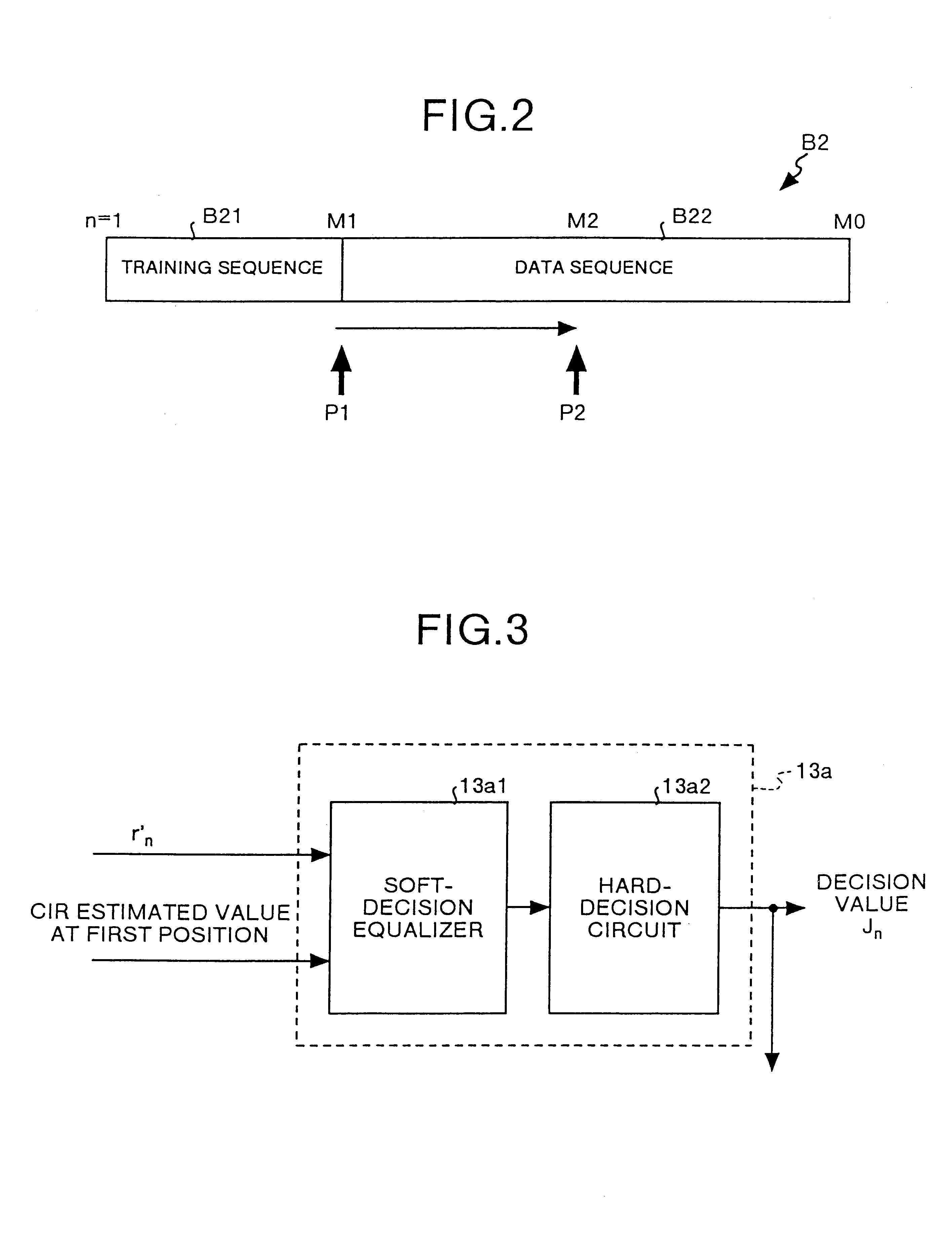
[0038]Also, the determining means comprises a soft-decision
equalizer for executing soft-decision of a data sequence in the corrected received signal according to the received signal corrected by the frequency offset correcting means as well as to the channel impulse response estimated value at the first position estimated by the first channel impulse response estimating means; and a hard-
decision circuit for executing hard decision of the soft-decision value estimated by the soft-decision
equalizer and outputting a result of the decision as a decision value of a data sequence in the received signal. Therefore, with this invention, decision can be made including reliability by the soft-decision equalizer, so that the reliability can be utilized in
forward error correction and so on.

