[0008]However, although the first valve control apparatus alleviates the problem suffered by the fully-electromagnetic valve control apparatus, due to its use of the electromagnetic valve actuating mechanism for part thereof, there still remains room for improvement in the following points: This valve control apparatus necessitates one electromagnetic valve actuating mechanism for one cylinder, and hence two electromagnets for one cylinder. This results in increased electric
power consumption, and decreases the advantageous effects of improvement of fuel economy thanks to the variable opening and closing timing of the intake valve, and compared with the ordinary cam-actuated type valve control apparatus, the weight and manufacturing costs are still large. Further, the maximum rotational speed of the engine available through the use of the electromagnetic valve actuating mechanisms is substantially determined by a spring constant of each
coil spring. This makes it necessary to set the spring constant of the
coil spring to a large value and accordingly electromagnets providing large attractive forces are also required to be employed, when the apparatus is applied to an
internal combustion engine whose maximum rotational speed is high (e.g. about 9000 rpm). This results in an increased electric
power consumption, and degrades fuel economy in low-to-medium rotational speed operating regions in which the engine is usually operated more frequently than in other regions, and makes it difficult to attain the improvement of fuel economy and the realization of higher rotational speed and higher
power output in a compatible fashion.
[0009]Further, the second valve control apparatus is only required to arrange one
electromagnet for one intake valve of each cylinder, and therefore has advantages over the first valve control apparatus in that it can further reduce the electric power consumption and improve the fuel economy. However, there remains room for improvement in the following points: In the second valve control apparatus, irrespective of whether the
electromagnetic actuator is active or inactive, the weight of the armature and the
spring force of the
impact-absorbing spring always act on the intake valve. This increases the
inertial mass of the intake valve in the inactive state of the
electromagnetic actuator, which restricts the maximum engine rotational speed and the maximum
power output. In this case, to increase the maximum engine rotational speed, it is necessary to increase the spring constant of the valve spring. This degrades fuel economy due to an increase in electric power consumption, and makes it impossible to attain the improvement of fuel economy and the realization of higher engine rotational speed and higher power output in a compatible fashion, or sufficiently reduce the weight and manufacturing costs. Further, in the case of this valve control apparatus, to
mount the solenoid, the armature, the
impact-absorbing spring therein, it is necessary to modify the designs of the
cylinder head and intake valves, at inevitably very high expenses.
[0010]This invention has been made with a view to providing a solution to these problems, and an object thereof is to provide a valve control apparatus for an internal
combustion engine that is capable of optimally setting the closing timing of an engine valve according to operating conditions of the engine while suppressing an increase in the
inertial mass of the engine valve to the minimum, thereby attaining improvement of fuel economy, and realization of higher engine rotational speed and higher power output in a compatible fashion, and reducing costs and weight thereof.DISCLOSURE OF INVENTION
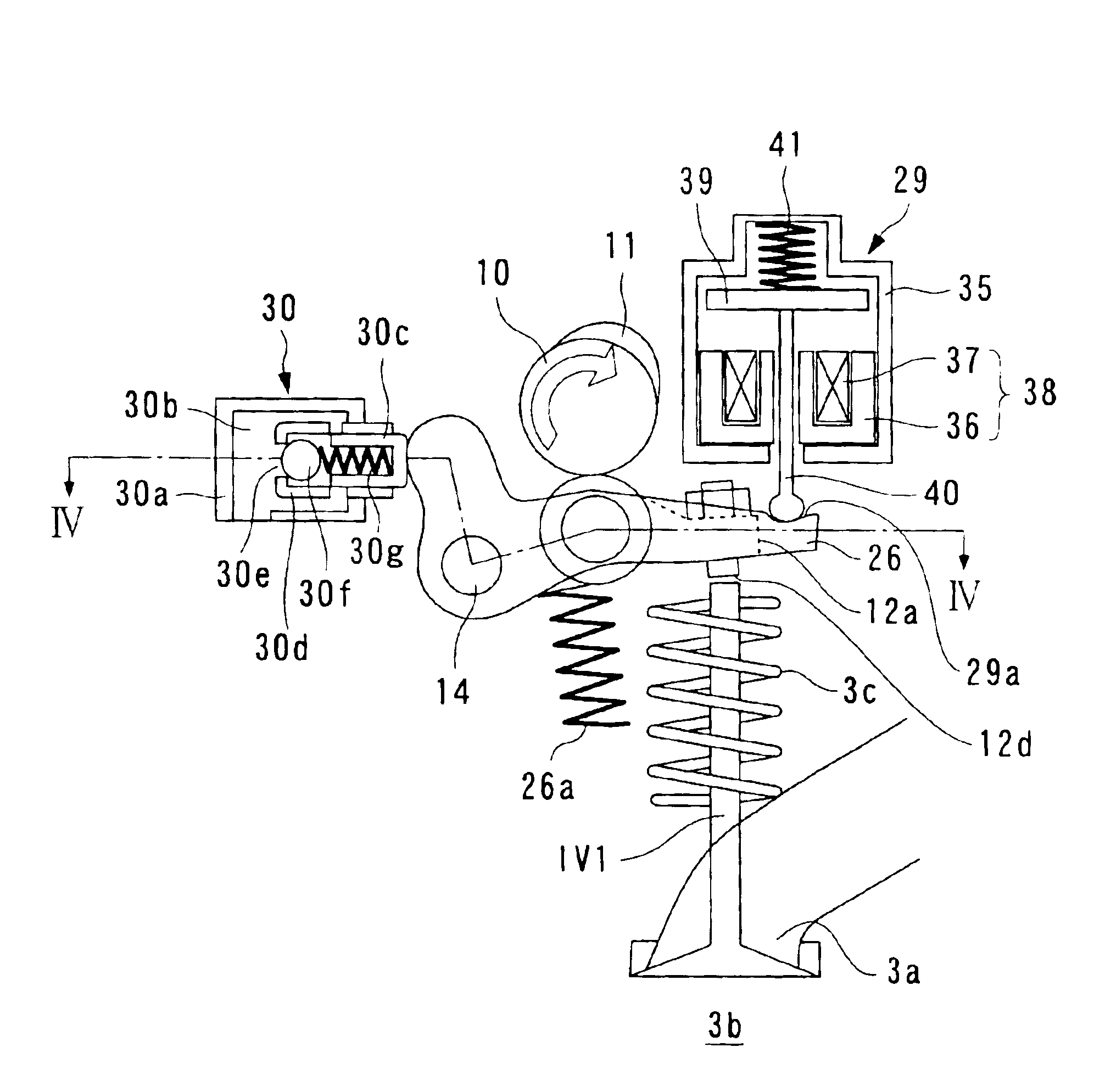
[0011]To attain the above object, the invention provides a valve control apparatus for an internal
combustion engine for controlling opening and closing operations of an engine valve, the valve control apparatus comprising a cam-type valve actuating mechanism that actuates the engine valve to open and close the engine valve, by a cam which is driven in
synchronism with rotation of the engine, an
actuator that makes blocking engagement with the engine valve having been opened, to thereby hold the engine valve in an open state, and control means for controlling operation of the actuator to thereby control closing timing of the engine valve.
[0012]According to this valve control apparatus for an internal
combustion engine, the engine valve is opened and closed by a cam driven in
synchronism with rotation of the cam-type valve actuating mechanism. Further, under the control of the control means, the actuator makes blocking engagement with the engine valve having been opened so as to hold the same in the open state, and further, by canceling the holding, the closing timing of the engine valve is controlled.
[0013]As described above, according to this invention, while actuating the engine valve by the cam-type actuating mechanism, the actuator is operated as required, whereby the closing timing of the engine valve can be controlled as desired. This makes it possible to attain the optimum fuel economy and power output adapted to operating conditions of the engine. For instance, when the engine valve is an intake valve, in a low-rotational speed / low-load condition, the closing timing of the intake valve is controlled to late closing according to the operating conditions of the engine, thereby reducing the pumping loss of the intake valve to the minimum, whereby the fuel economy can be enhanced. On the other hand, in the high-rotational speed / high-load region, the actuator is made inactive, and only the cam-type valve actuating mechanism actuates the intake cam, whereby the higher rotational speed and higher power output can be attained without being affected by the follow-up capability of the actuator. Further, when the engine valve is an
exhaust valve, by varying the closing timing of the
exhaust valve, the overlap amount is controlled, whereby the power output can be improved and the exhaust emissions can be reduced.

