Apparatus and method of wireless data transmission

a wireless data and apparatus technology, applied in the direction of process and machine control, optical radiation measurement, instruments, etc., can solve the problems of inability to adapt, gradual degradation of sensor lenses, gradual degradation of ir emitter performance, etc., to achieve faster information transfer, preventive maintenance, and reduce maintenance costs

Inactive Publication Date: 2005-10-18
GEBERIT INT AG
View PDF40 Cites 59 Cited by
  • Summary
  • Abstract
  • Description
  • Claims
  • Application Information

AI Technical Summary

Benefits of technology

[0010]There is a need for an improved fluid dispensing system that overcomes many of the shortcomings associated with conventional automatically activated flow control devices. Such a system should provide for improved maintenance including better preventive maintenance, reduced cost of maintenance, troubleshooting help, faster transfers of information, and recording of information related to maintenance. It would further be desirable if the dispensing device consumed low power, was capable of being retrofitted into existing dispensing devices, easy to install, and low cost.
[0017]The remotely managed automatic dispensing apparatus and method of the present invention results in a number of advantages over other devices and methods commonly known in the art. For example, the remotely managed automatic dispensing apparatus and method of the present invention provide for the efficient servicing and maintenance of multiple remotely managed automatic dispensing apparatuses positioned in a single room, such as a public restroom. In accordance with the invention, maintenance personnel may simply enter the room with a portable communication device and determine which if any of the remotely managed automatic dispensing apparatuses are defective, or otherwise require servicing.

Problems solved by technology

A common denominator for many of the problems associated with automatically activated flow control devices, such as faucets, is the environment in which such devices are installed and operate.
For instance, existing IR sensor designs generally suffer from an inability to adapt to changes in the background signal level associated with a gradual discoloration of the sink in which the faucet is mounted, a gradual degradation of the sensor lens due to the use of abrasive cleaning compounds, a gradual degradation of the IR emitter performance, among other things.
When the IR sensor sensitivity is fixed, the sensors performance will inevitably degrade with environmental changes, and when the degradation causes faulty operation, a service call may be required.
In some instances, the gradual degradation will go unnoticed resulting in poor performance.
When the IR emitter is mounted behind the aerator of the faucet, as is commonly done in the art, near-IR light is reflected back from the water stream to the IR receiver causing the water to remain on, which results in a waste of water and annoyance to the user.
Inconsistent lighting conditions, as well as water and / or soap film deposits on the optical lens of the IR sensors also cause faulty operation of an automatic flow device, such as a faucet or other device activated via IR sensing.
In addition, paper towels or other debris left in the sink basin can induce misleading reflections to the IR receiver.
Servicing and maintenance of presently available automatically activated flow control devices are often burdensome and time-consuming tasks.
Such tasks prove particularly burdensome for maintenance personnel in settings such as public restrooms where there are a number of automatically activated flow control devices, such as faucets or toilets, in a single room.
Such tasks may be time consuming and difficult to accomplish given the location of the device electronics (usually beneath, behind or under the counter top, toilet, or other structure supporting the device).
Likewise, updating or enhancing the software or electronics of these devices usually requires maintenance personnel to access the device electronics.
In addition, calibration of today's automatically activated flow control devices is often labor intensive and inefficient with respect to devices presently on the market.
As a result, readings taken by these IR sensing units (such as whether a user's hands are present beneath the aerator of a faucet) are generally non-uniform from device to device and, therefore, often result in improper activation and deactivation of some devices.
Unfortunately, vandalism and water damage also adversely affect the use and proper operation of automatically activated flow control devices presently available in the art.
Water often travels along the wiring harness extending from the flow control device to the device's electronics causing corrosion to the parts.
On occasion, vandals may attempt to break into the electronics box associated with the device or pull the wires from either the electronics box or the faucet.

Method used


Image

  • Apparatus and method of wireless data transmission
  • Apparatus and method of wireless data transmission
  • Apparatus and method of wireless data transmission

Examples


Embodiment Construction

[0031]Because the novel and patentable features of the present invention can be shown with block and other diagrams, conventional electronic elements well known to those skilled in the art, such as transistors, amplifiers, resistors, capacitors, programmable processors, logic arrays, memories and corresponding couplings and connections of such elements are not shown. A person skilled in the art could readily understand the block diagrams illustrating embodiments of the present invention. The block diagrams show specific details that are pertinent to the present invention and do not obscure the disclosure with details that would readily be apparent to those skilled in the art.

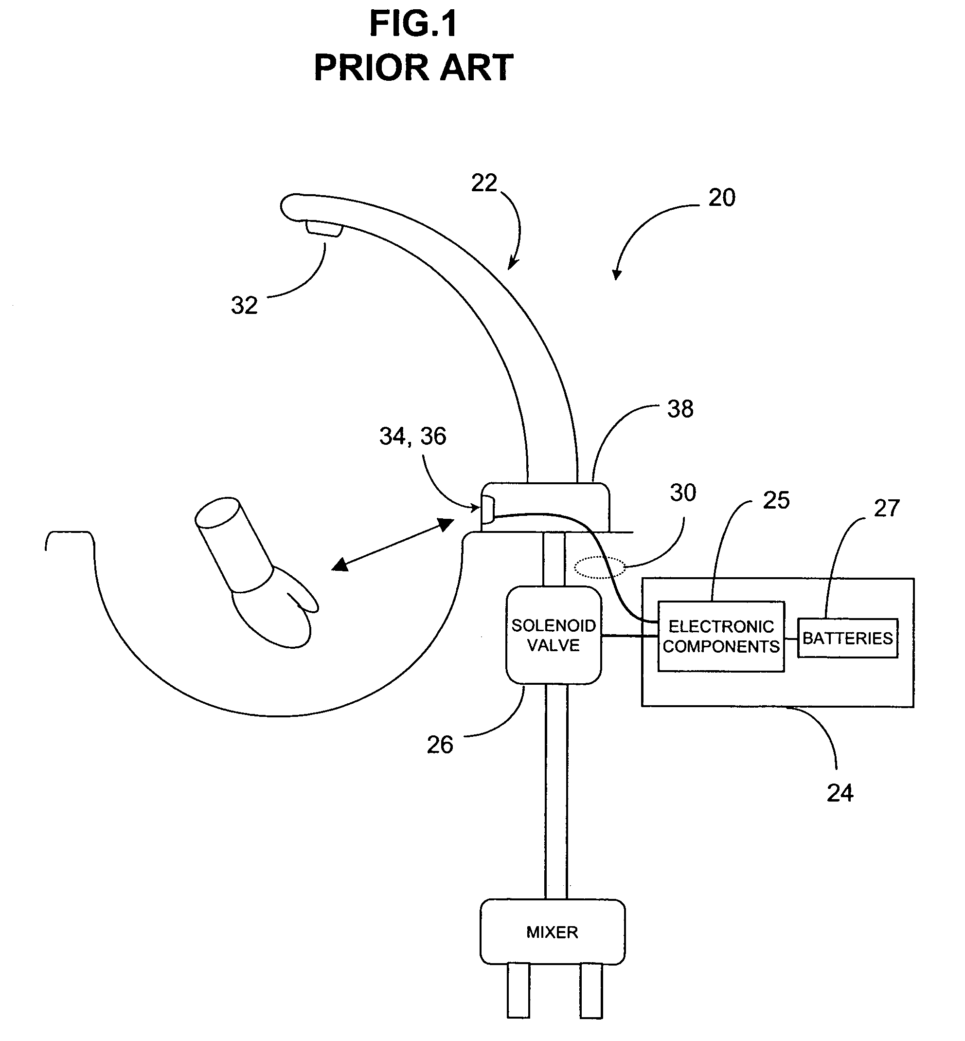
[0032]A conventional electronically operated flow control device 20 commonly found in the art is shown in FIG. 1. The prior art embodiment depicted in FIG. 1 generally includes a faucet 22, an electronics box 24 for housing electronic components 25 and batteries 27. The electronic components 25 are coupled to a ...


PUM


Abstract

A remotely managed electronically operated dispensing apparatus having a transmitter for transmitting a detection signal and a communication signal is disclosed. When the detection signal is reflected from an object, the dispensing apparatus opens a valve allowing fluid to flow. The communication signal may contain maintenance, status and other information and is received by a communication device.

Description

CROSS-REFERENCE TO RELATED APPLICATIONS[0001]This application claims the benefit of U.S. Provisional Patent Application Ser. No. 60 / 267,441 entitled, “Remotely Managed Automatic Dispensing Apparatus and Method”, filed on Feb. 8, 2001, and U.S. Provisional Patent Application Ser. No. 60 / 242,898 entitled, “Remotely Managed Automatic Dispensing Apparatus and Method”, filed on Oct. 24, 2000, both of which are hereby incorporated by reference herein.FIELD OF THE INVENTION[0002]The present invention relates generally to the field of electronic or automatic flow control and dispensing devices and more particularly to data exchange by such devices. While the present invention is applicable for use with any number of dispensing devices, it is particularly well suited for the operation, management, and control of devices that control water flow, such as faucets, toilets, shower heads, and the like.BACKGROUND OF THE INVENTION[0003]Various methods have been employed to electronically control wa...

Claims


Application Information

Patent Timeline
Patent Type & Authority Patents(United States)
IPC IPC(8): G07F13/06G07F13/00G07F9/02G07F13/02
CPCG06Q20/327G07F9/026G07F13/025G07F13/065G08C2201/42G08C2201/51
Inventor PATTERSON, WADE C.WATSON, THOMAS J.
Owner GEBERIT INT AG
Why Eureka
Try Eureka