LCD driver

a technology of liquid crystal display and driver, applied in the field of lcd driver, can solve the problems of disadvantageous increase in the complexity of the circuit of the lcd driver, and achieve the effect of simple structur

Inactive Publication Date: 2005-10-18
ROHM CO LTD
View PDF8 Cites 14 Cited by
  • Summary
  • Abstract
  • Description
  • Claims
  • Application Information

AI Technical Summary

Benefits of technology

[0020]In an LCD driver according to the invention, the visual luminance of the LCD can be corrected in accord with a given image signal without any palette circuit for converting the input image signal itself. Thus the driver circuit has a simple structure.
[0021]It should be appreciated that a low-frequency clock is used when the count of the counter lies in a near-lower limit domain and a near-upper limit domain of the image signal so that the width of one step of the PWM is larger in these domains to compensate for the nonlinearity of the S-shape transmittance characteristic.

Problems solved by technology

Hence, the conventional PWM voltage generator requires a palette circuit as discussed above, which circuit disadvantageously increases complexity of the LCD driver, contrarily to a need for simplification of the driver.

Method used


Image

  • LCD driver
  • LCD driver
  • LCD driver

Examples


Embodiment Construction

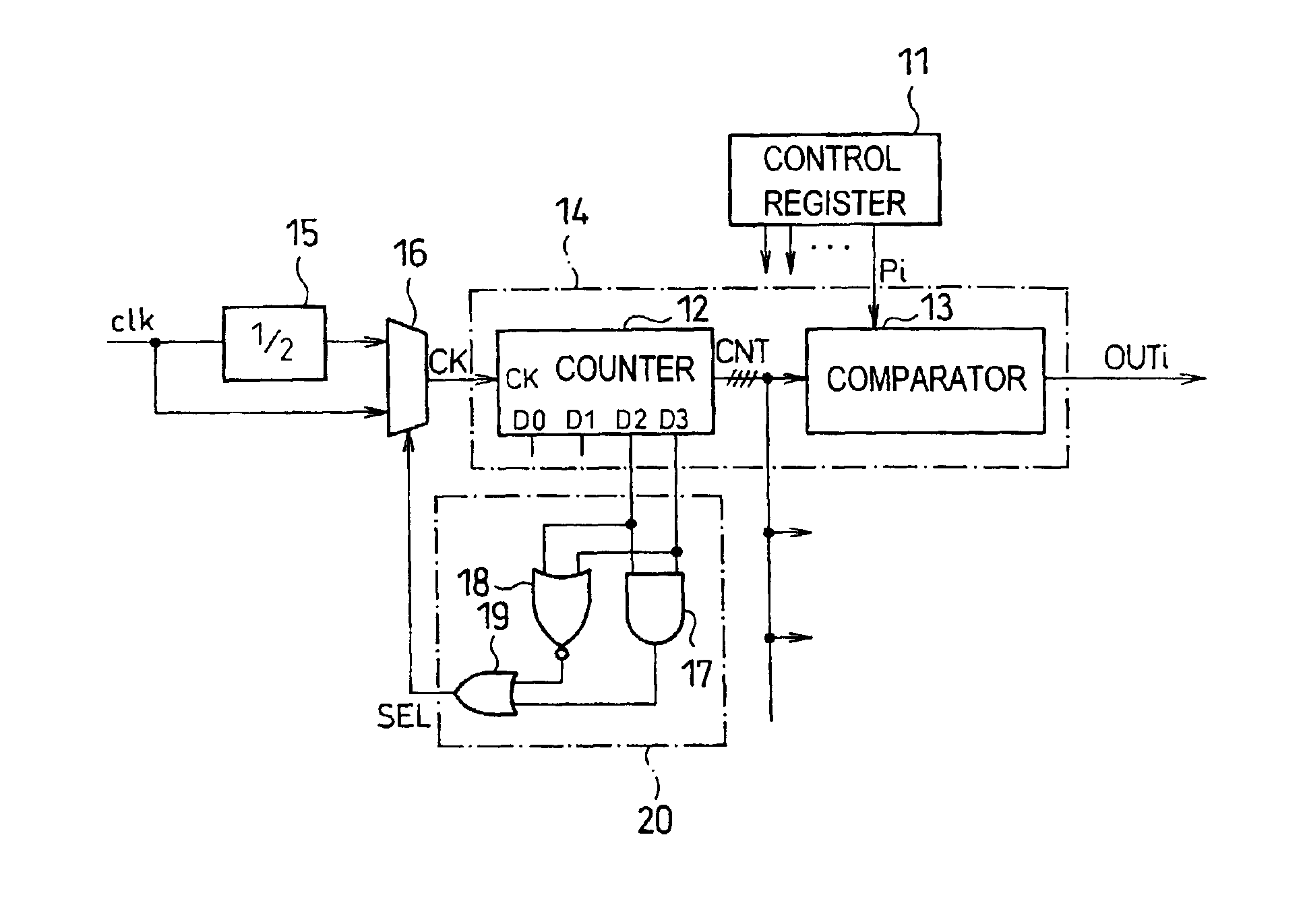
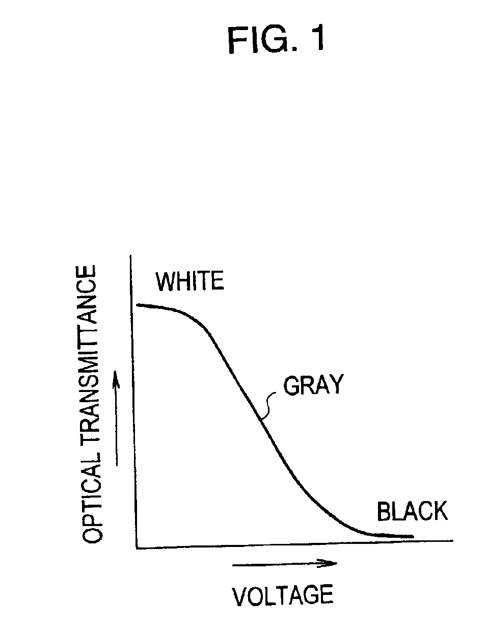
[0027]FIG. 3 is a block diagram of an LCD driver according to one embodiment of the invention. FIG. 4 is a timing diagram of the LCD driver. FIG. 5 shows a relationship between duty factors of PWM and the magnitude of an input signal.

[0028]As shown in FIG. 3, a control register 11 stores the image signals Pi to be displayed on an LCD, in the form of digital data (referred to as digital image data). The control register 11 sequentially updates and outputs digital image data (or digital image signals) Pi. The control register 11 is configured to output in parallel a multiplicity of image signals Pi to be displayed simultaneously on the LCD.

[0029]A PWM circuit 14 receives an input clock CK and the image signals Pi, and outputs a PWM signal for each of the image signals. In order to deal with the multiple image signals Pi simultaneously, the PWM circuit 14 has a counter 12 and the same number of parallel comparators 13 as the number of signals Pi. It is noted that the counter 12 is comm...


PUM

PropertyMeasurementUnit
frequencyaaaaaaaaaa
frequency-division factoraaaaaaaaaa
frequenciesaaaaaaaaaa

Abstract

An LCD driver compares an image signal with a count of a counter repeatedly counting a clock. Based on the result of the comparison, the LCD driver outputs pulses each having a duty factor in accord with the image signal. When the count is not between first and second predetermined numbers, the frequency of the clock supplied to the counter is switched from a fundamental frequency to a low-frequency, thereby controlling the width of a drive voltage of a liquid crystal display cell and correcting the image signal in association with the S-shape characteristic of optical transmittance of the liquid crystal display cell. This LCD driver is advantageously simple in structure.

Description

FIELD OF THE INVENTION[0001]The invention relates to a liquid crystal display (LCD) driver for providing a drive voltage corrected by pulse-width modulation (PWM) in accord with an image signal.BACKGROUND OF THE INVENTION[0002]LCDs are commonly used as means for displaying images. The optical transmittance of a liquid crystal depends on the voltage applied to it. This property is utilized in an LCD to control the luminance of a liquid crystal by controlling the voltage applied to it to thereby control the amount of light emitted from a source of light and passing through the liquid crystal.[0003]The optical transmittance of liquid crystal is not a linear function of the applied voltage. A typical TN-type or STN-type liquid crystal has a substantially linear optical transmittance only in the intermediate region of its operating voltage and has slowly varying nonlinear transmittance above and below the linear region, as shown in FIG. 1. Thus, an overall optical transmittance of a liqu...

Claims


Application Information

Patent Timeline
Patent Type & Authority Patents(United States)
IPC IPC(8): G02F1/133G02F1/13G09G3/36G09G3/20
CPCG09G3/3692G09G3/2014
Inventor NAIKI, TAKASHI
Owner ROHM CO LTD
Why Eureka
Try Eureka