Rapid response power conversion device

a power conversion device and rapid response technology, applied in the direction of engines without rotary main shafts, machines/engines, mechanical equipment, etc., can solve the problems of engine not being able to reach the desired change in a very rapid fashion, limitation is particularly problematic, and has not been successfully used in many applications. , to achieve the effect of superior bandwidth characteristics of the engin

Inactive Publication Date: 2005-10-25
SARCOS LC
View PDF11 Cites 20 Cited by
  • Summary
  • Abstract
  • Description
  • Claims
  • Application Information

AI Technical Summary

Benefits of technology

[0011]The present invention relates to an apparatus and method for extracting a portion of energy from the energy created during combustion in an internal combustion engine. The present invention is directed to extracting a portion of energy during an optimal time period of combustion and providing superior bandwidth characteristics to the engine.

Problems solved by technology

While primary power sources have been successfully used to perform these functions, they have not been successfully used independently in many applications because of their relatively slow response characteristics.
This limitation is particularly problematic in powering robotic devices and similar systems which utilize a feedback loop which makes real time adjustments in movements of the mechanical structure.
But the engine cannot reach the desired change in a very rapid fashion due to inertial forces internal to the engine and the nature of the combustion process.
Moreover, if it is attempted to operate the engine repeatedly in a rapid cycle from 0 to 7000 rpms and back to 0 rpms, the response time of the engine slows even further as the engine attempts to respond to the cyclic signal.
Heavy equipment is generally powered by an internal combustion engine, usually a diesel engine, which supplies ample power for the operation of the equipment, but is incapable of meeting the energy response requirements of the various components.
However, this versatility comes at a cost.
In order for a system to be energetically autonomous and be capable of precise control, more components must be added to the system, increasing weight and cost of operation of the system.
However, in order to use electric power in a system without tethering the system to the power grid, the system must be configured to use energy storage devices such as batteries, which can be very large and heavy.
As modern technology moves into miniaturization of devices, the extra weight and volume of the power source and its attendant conversion hardware are becoming major hurdles against meaningful progress.
The complications inherent in using a primary power source to power a rapid response source become increasingly problematic in applications such as robotics.
To date, however, technology has struggled to realize this combination of rapid response, minimal weight, effective control, and autonomy of operation.

Method used


Image

  • Rapid response power conversion device
  • Rapid response power conversion device
  • Rapid response power conversion device

Examples


second embodiment

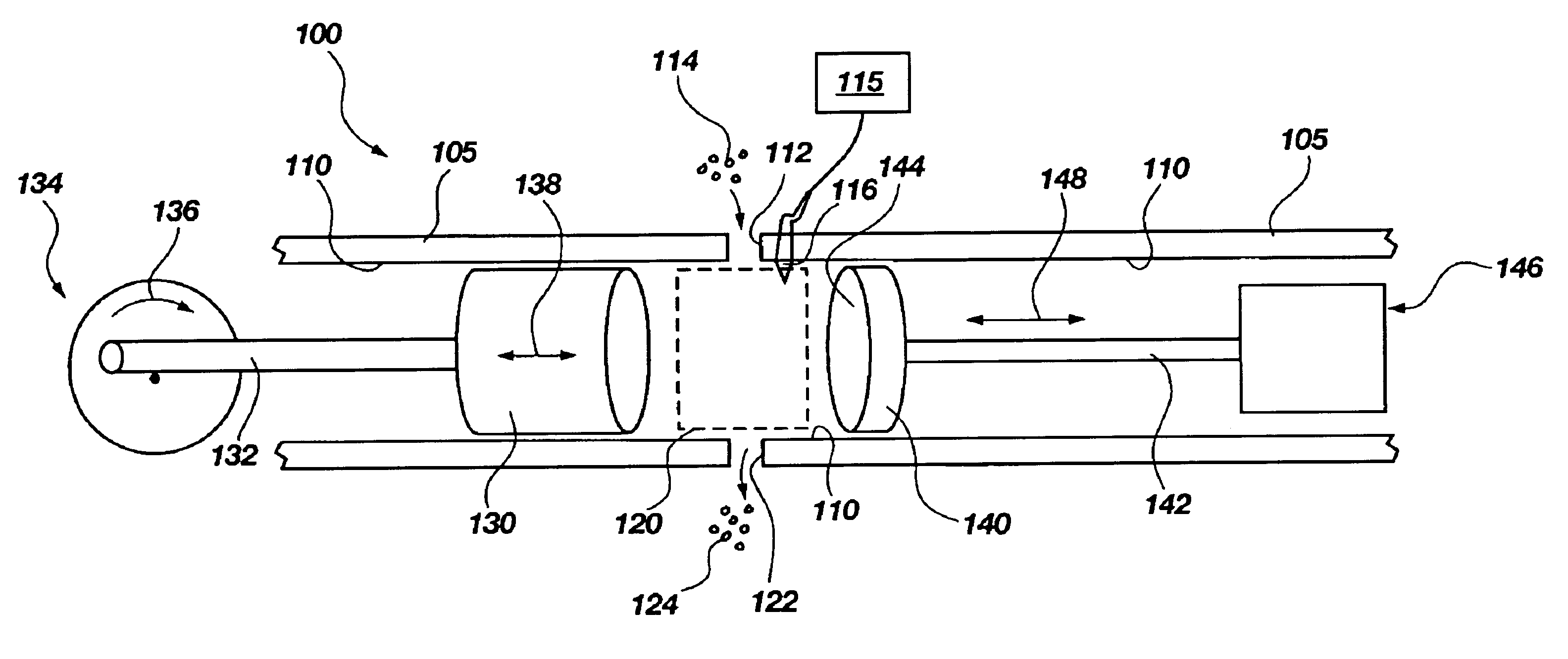
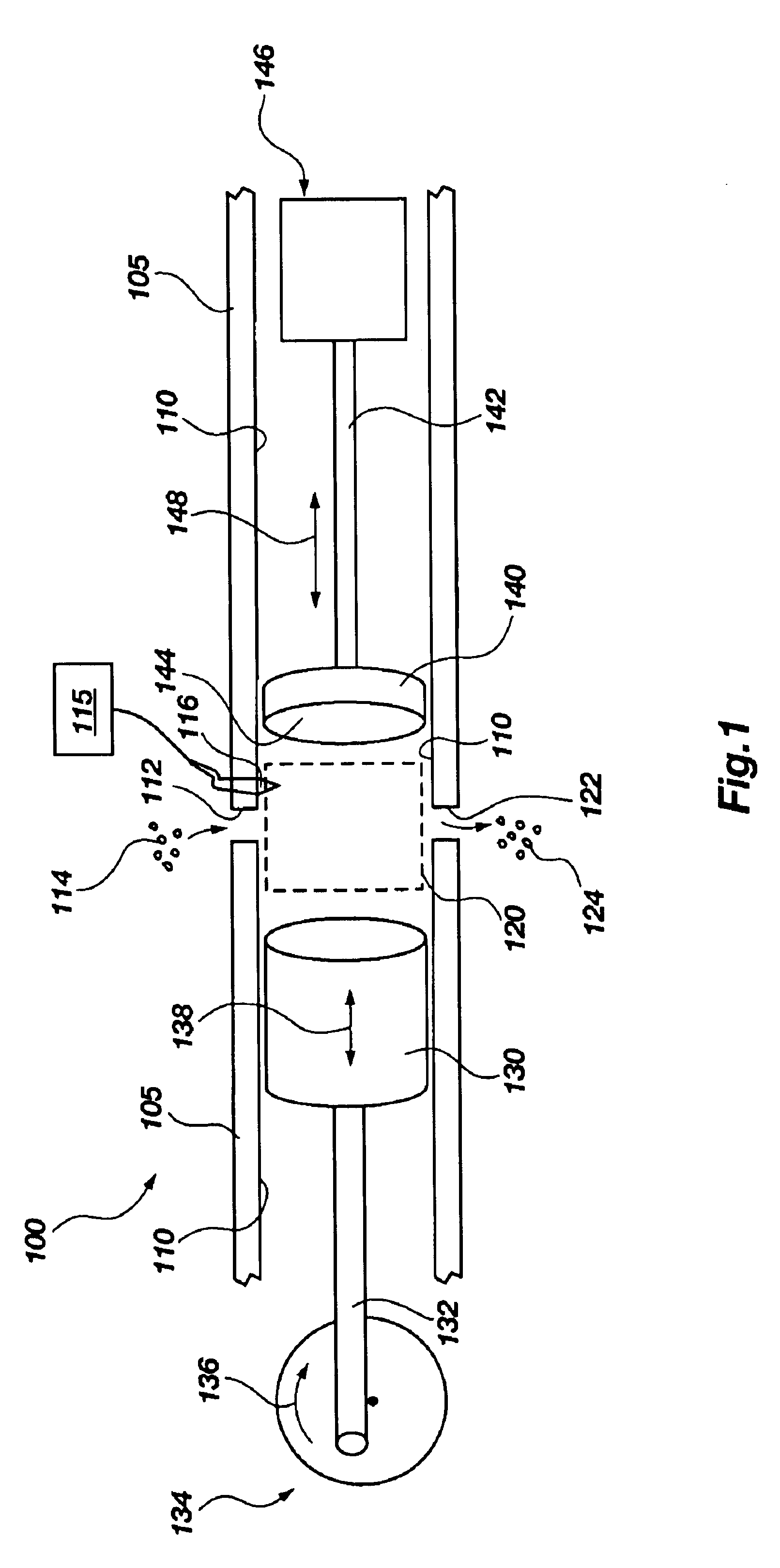
[0042]In the second embodiment, the primary piston 230 may reciprocate via combustion or an electric power source to push the fuel 214 from the first compartment to the second compartment of chamber 210. By having a divider portion 250, the combustion at the combustion portion 220 of the chamber 210 can be at least partially, or even totally, isolated from the primary piston 230. Depending on the requirements of the system 200, the controller 215 may be configured to open or close aperture 252 at varying degrees to isolate combustion from the primary piston 230. As such, in the instance of total isolation, a maximum amount of energy to the secondary piston 240 may be transferred by a rapid response to combustion. It is also contemplated that the primary piston 230 in the first compartment 254 may include a positive displacement compressor and / or an aerodynamic compressor, such as a centrifugal compressor.

[0043]Referring now to FIGS. 1 and 4, a graphical diagram of the physical respo...

third embodiment

[0052]Referencing FIG. 8, the rapid response energy extracting system 700 may be provided in a non-combustion engine, according to the present invention. The system 700 includes a chamber 710 with a primary piston 730 and a secondary piston 740. Instead of internal combustion provided by fuel and oxygen, a fluid 714, such as a monopropellant or hydrogen peroxide, may enter through an intake port 712 of the chamber 710. The fluid 714 may pass through or over a reaction member 720, such as a catalyst or heat-exchanger. Such a catalyst may include silver, silver alloy, and / or a silver / ceramic material. As the fluid 714 passes over the reaction member 720, a rapid non-combustive reaction results, which may include rapid decomposition of the fluid 714 and / or vaporization of the fluid 714. As in the IC engine, such rapid non-combustive reaction causes a rapid response from the secondary piston 740 for extracting a portion of energy from the rapid non-combustive reaction. In this system, t...


PUM


Abstract

An apparatus and method for extracting energy from an internal combustion engine includes a chamber having a primary piston and a secondary piston with a combustion portion of the chamber situated adjacently between the primary piston and secondary piston. The secondary piston includes a substantially lesser mass than that of the primary piston. The chamber includes at least one fluid port for supplying fuel to the combustion portion and an out-take port for releasing combustive exhaust. The chamber includes a controller for controlling the combustion therein at selected cycles of the primary piston. The secondary piston is configured to draw a portion of energy from combustion controlled by the controller in the chamber. Such portion of energy is provided with a rapid response to an energy transferring portion interconnected to the secondary piston, which in turn, transfers and/or converts the energy for acting on a load or external application.

Description

[0001]Priority of application No. 60 / 303,053 filed Jul. 5, 2001 in the US Patent Office is hereby claimed.BACKGROUND OF THE INVENTION[0002]1. Field of the Invention[0003]The present invention relates generally to internal combustion engines. More specifically, the present invention relates to an apparatus and method of extracting energy from combustion in an internal combustion engine.[0004]2. Related Art[0005]Primary power sources that directly convert fuel into usable energy have been used for many years in a variety of applications including motor vehicles, electric generators, hydraulic pumps, etc. Perhaps the best known example of a primary power source is the internal combustion engine, which converts fossil fuel into rotational power. Internal combustion engines are used by almost all motorized vehicles and many other energetically autonomous devices such as lawn mowers, chain saws, and emergency electric generators. Converting fossil fuels into usable energy is also accompli...

Claims


Application Information

Patent Timeline
Patent Type & Authority Patents(United States)
IPC IPC(8): F02B75/28F02B75/00F02B75/02F01B11/00
CPCF01B11/00F02B75/28F02B75/285F02B2075/025F02B2075/027
Inventor JACOBSEN, STEPHEN C.OLIVIER, MARC
Owner SARCOS LC
Why Eureka
Try Eureka