Method of electroplating copper over a patterned dielectric layer to enhance process uniformity of a subsequent CMP process

Inactive Publication Date: 2005-10-25
GLOBALFOUNDRIES INC
View PDF15 Cites 10 Cited by
  • Summary
  • Abstract
  • Description
  • Claims
  • Application Information

AI Technical Summary

Benefits of technology

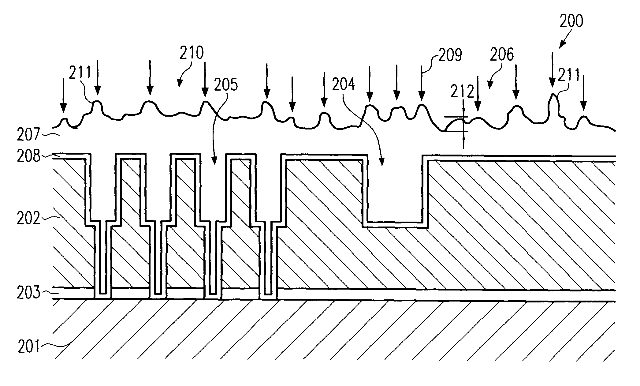
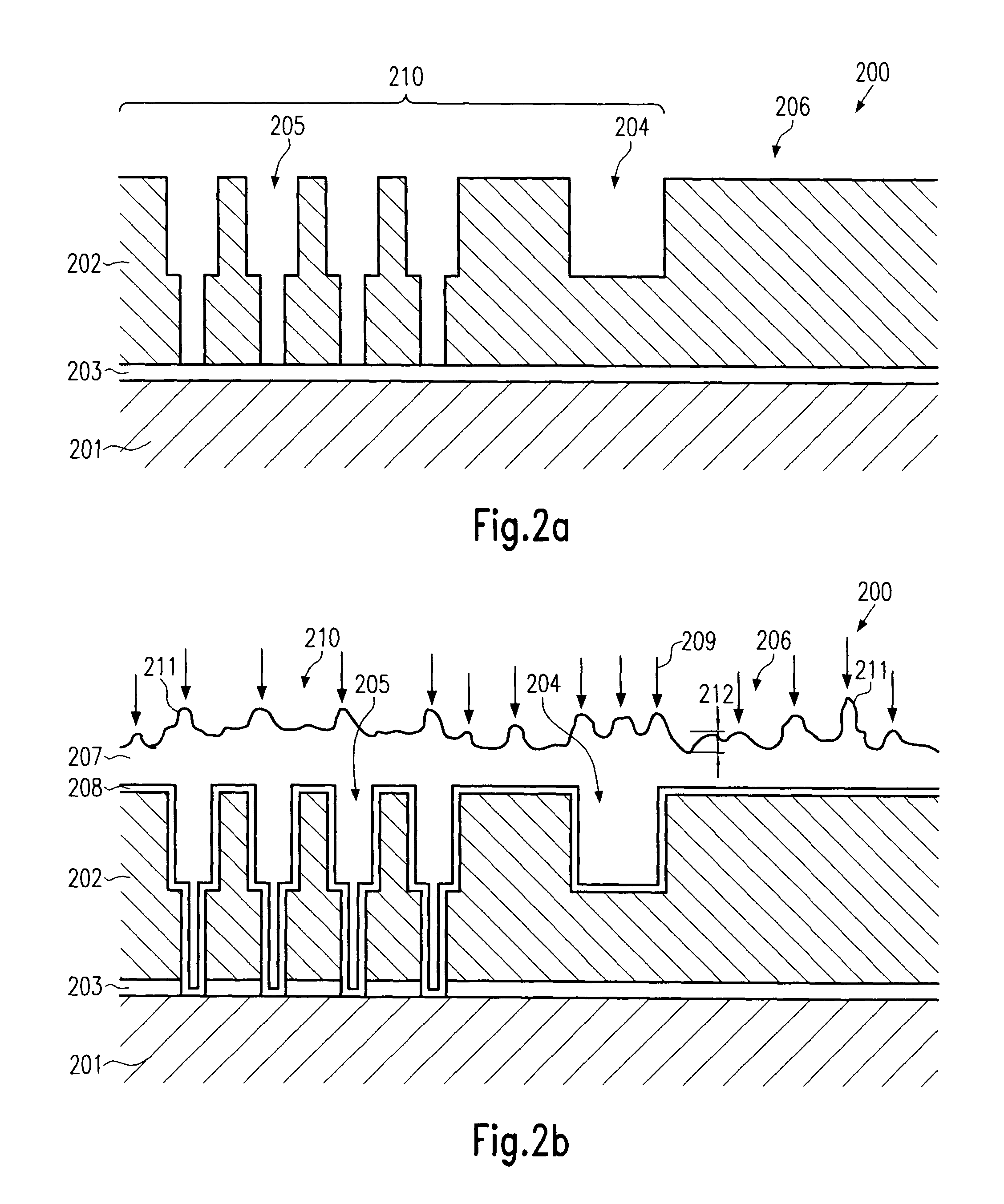
[0014]Generally, the present invention is directed to methods that may improve the uniformity of a CMP process in that a preceding sequence for forming a plated metal layer is modified so as to provide a significant surfa

Problems solved by technology

In every new generation of integrated circuits, device features are further reduced, whereas the complexity of the circuits steadily increases.
Despite the many advantages of copper compared to aluminum, semiconductor manufacturers in the past have been reluctant to introduce copper into the manufacturing sequence for several reasons.
One major issue in processing copper in a semiconductor line is the copper's capability of readily diffusing in silicon and silicon dioxide at moderate temperatures.
Copper diffused into silicon may lead to a significant increase in the leakage current of transistor elements, since copper acts as a deep-level trap in the silicon band-gap.
Moreover, copper diffused into silicon dioxide may compromise the insulating properties of silicon dioxide and may lead to higher leakage currents between adjacent metal lines, or may even form shorts between neighboring metal lines.
A further issue arises from the fact that copper may not be effectively applied in greater amounts by deposition methods, such as physical vapor deposition (PVD) and chemical vapor deposition (CVD), which are well-known and well-established techniques in depositing other materials, such as aluminum.
Although at a first glance electroplating seems to be a relatively simple and well-established deposition method due to the great amount of experience gathered in the printed wiring board industry during decades, the demand

Method used


Image

  • Method of electroplating copper over a patterned dielectric layer to enhance process uniformity of a subsequent CMP process
  • Method of electroplating copper over a patterned dielectric layer to enhance process uniformity of a subsequent CMP process
  • Method of electroplating copper over a patterned dielectric layer to enhance process uniformity of a subsequent CMP process

Examples


Embodiment Construction

[0025]Illustrative embodiments of the invention are described below. In the interest of clarity, not all features of an actual implementation are described in this specification. It will of course be appreciated that in the development of any such actual embodiment, numerous implementation-specific decisions must be made to achieve the developers' specific goals, such as compliance with system-related and business-related constraints, which will vary from one implementation to another. Moreover, it will be appreciated that such a development effort might be complex and time-consuming, but would nevertheless be a routine undertaking for those of ordinary skill in the art having the benefit of this disclosure.

[0026]The present invention will now be described with reference to the attached figures. Although the various regions and structures of a semiconductor device are depicted in the drawings as having very precise, sharp configurations and profiles, those skilled in the art recogni...


PUM


Abstract

In a new method of plating metal onto dielectric layers including small diameter vias and large diameter trenches, a surface roughness is created at least on non-patterned regions of the dielectric layer to enhance the uniformity of material removal in a subsequent chemical mechanical polishing (CMP) process.

Description

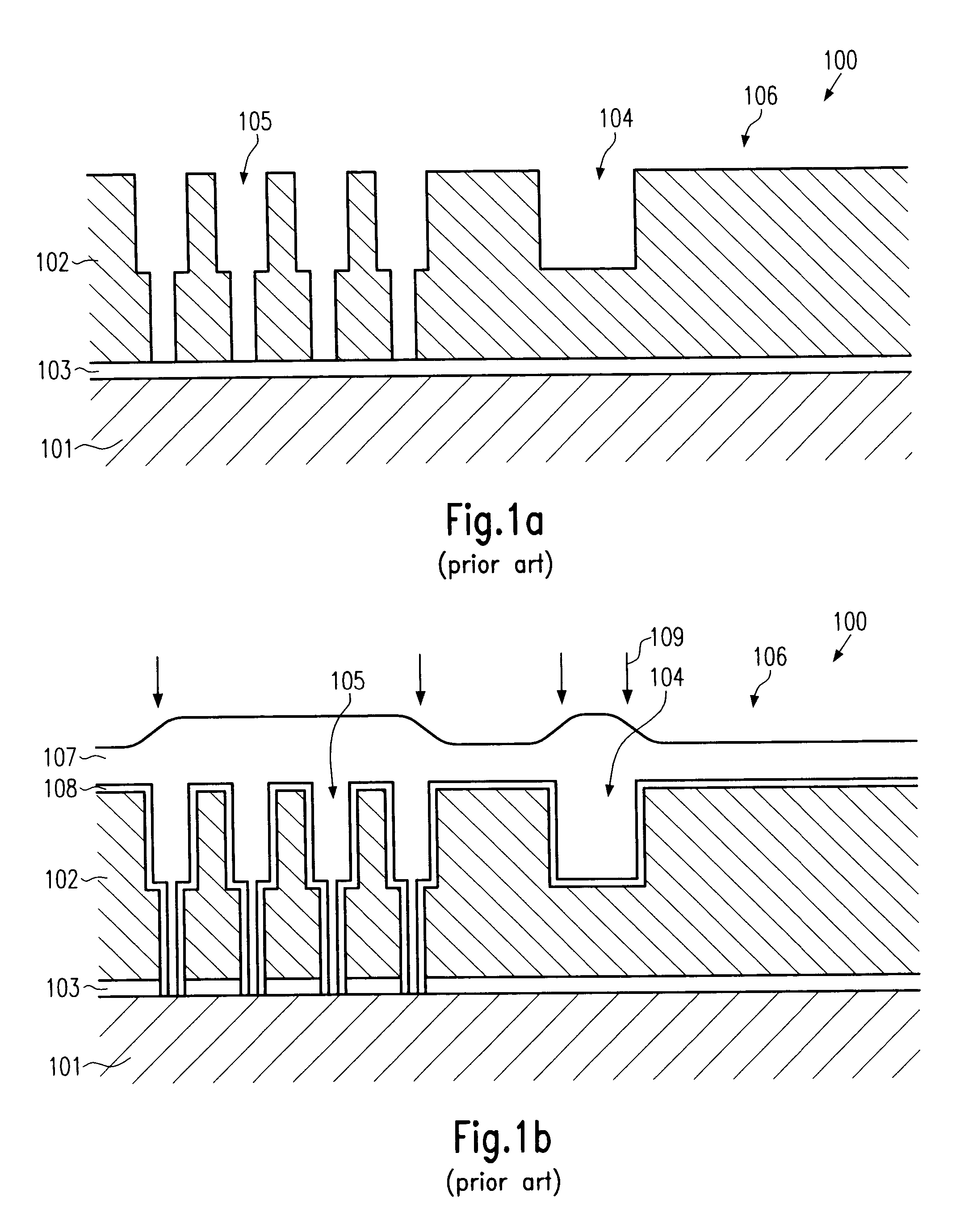
BACKGROUND OF THE INVENTION[0001]1. Field of the Invention[0002]The present invention generally relates to the fabrication of integrated circuits, and, more particularly, to the formation of metallization layers, wherein a metal is deposited over a patterned dielectric layer and excess metal is subsequently removed by chemical mechanical polishing (CMP).[0003]2. Description of the Related Art[0004]In every new generation of integrated circuits, device features are further reduced, whereas the complexity of the circuits steadily increases. Reduced feature sizes not only require sophisticated photolithography methods and advanced etch techniques to appropriately pattern the circuit elements, but also places an ever-increasing demand on deposition techniques. Presently, the minimum feature sizes approach 0.1 μm or even less, which allows the fabrication of fast-switching transistor elements covering only a minimum of chip area. However, as a consequence of the reduced feature sizes, th...

Claims


Application Information

Patent Timeline
IPC IPC(8): H01L21/70H01L21/288H01L21/02H01L21/768
CPCH01L21/2885H01L21/76877H01L21/7684
Inventor MARXSEN, GERDPREUSSE, AXELNOPPER, MARKUSMAUERSBERGER, FRANK
Owner GLOBALFOUNDRIES INC
Why Eureka
Try Eureka