
SOI semiconductor configuration and method of fabricating the same

a technology of semiconductors and configurations, applied in the direction of semiconductor devices, electrical equipment, transistors, etc., can solve the problem of a hot charge carrier being considered a lot more difficult to break

Inactive Publication Date: 2005-10-25
POLARIS INNOVATIONS LTD
View PDF9 Cites 15 Cited by
  • Summary
  • Abstract
  • Description
  • Claims
  • Application Information

AI Technical Summary

Benefits of technology

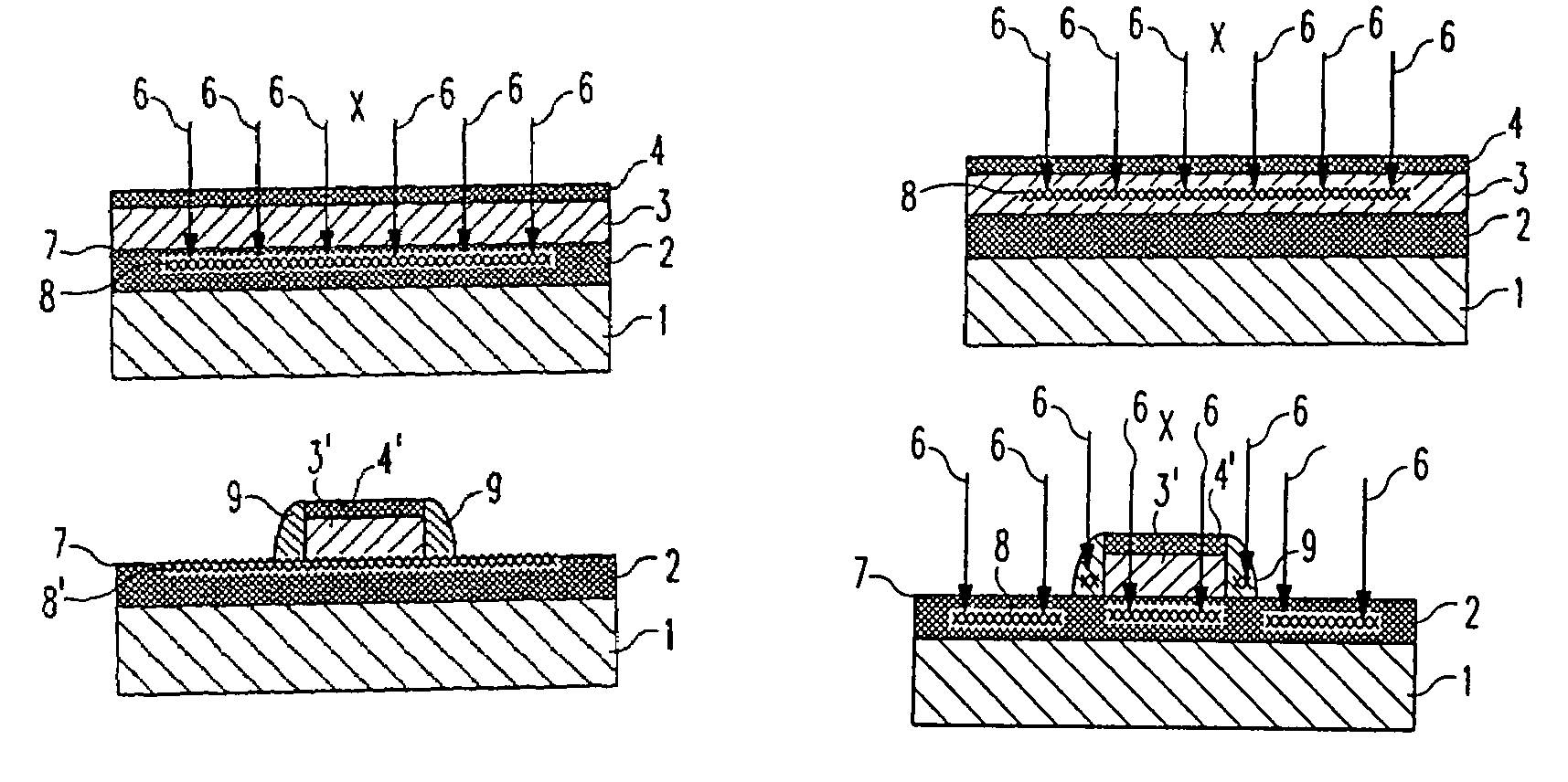
"The invention provides a semiconductor configuration that overcomes the disadvantages of conventional SOI devices by incorporating a passivating substance that forms Si—X bonds at the interface between the insulation layer and the monocrystalline silicon layer. These Si—X bonds have greater bond energy than Si—H bonds, making it difficult for hot charge carriers to rupture them. The semiconductor configuration can be used to form high-performance SOI transistors with reduced damage to the insulation layer and improved transistor properties. The method of fabricating the semiconductor configuration involves introducing the passivating substance into one of the insulation layer and the monocrystalline silicon layer and heat-treating it to cause the passivating substance to diffuse into the region of the interface and replace existing Si—H bonds with Si—X bonds."

Problems solved by technology

Since the Si—X bonds have a greater bond energy than Si—H bonds, it is considerably more difficult for hot charge carriers to rupture them.

Method used


Image

  • SOI semiconductor configuration and method of fabricating the same
  • SOI semiconductor configuration and method of fabricating the same
  • SOI semiconductor configuration and method of fabricating the same

Examples


Embodiment Construction

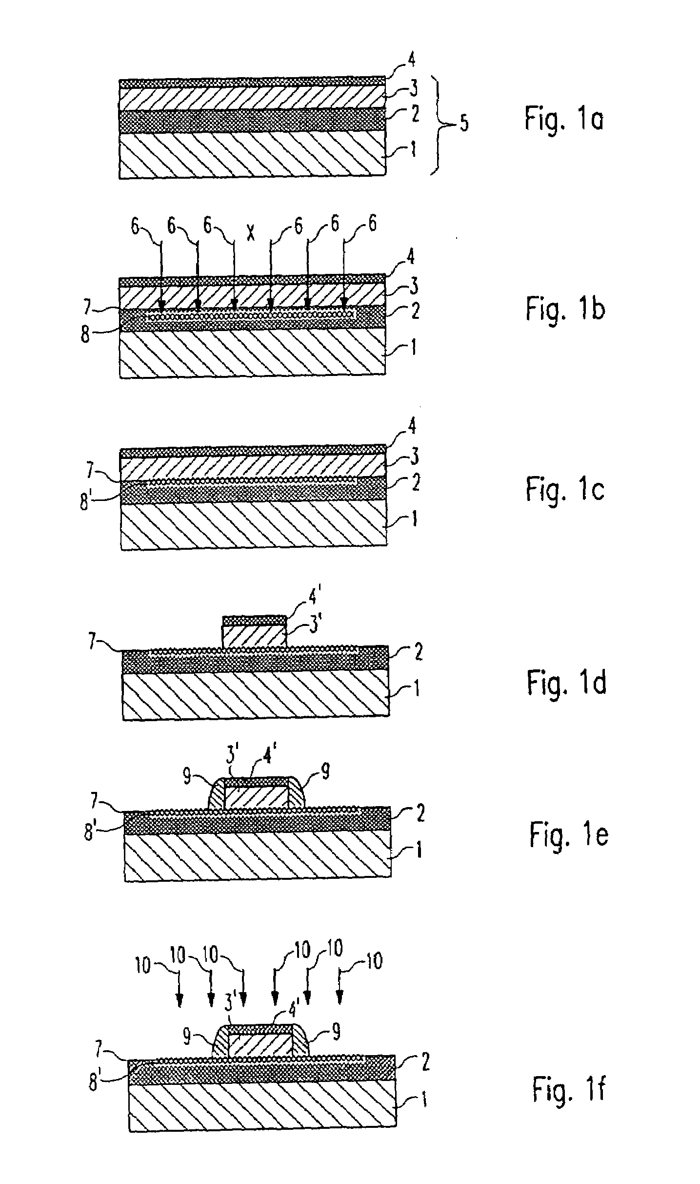
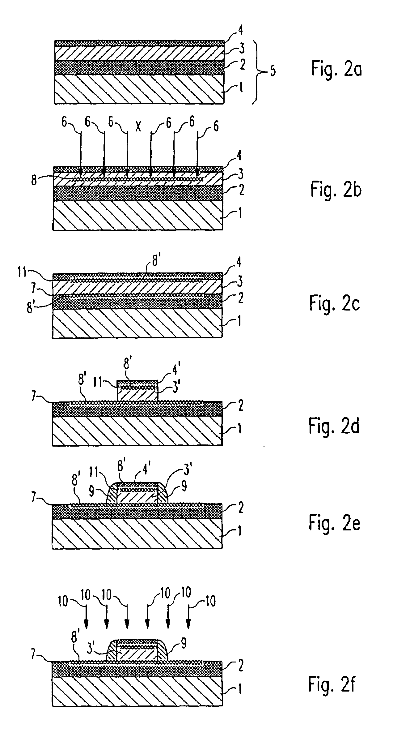
[0038]Referring now to the figures of the drawing in detail and first, particularly, to FIGS. 1a to 1f thereof, there is seen an SOI semiconductor structure 5 that comprises an Si base layer 1, which is formed by an Si substrate and is adjoined by a buried oxide layer 2, on which a monocrystalline silicon layer 3 is overlaid. By way of example, the SOI semiconductor structure 5 may be fabricated according to the SIMOX or BESOI technologies and is commercially available as a finished product. Furthermore, the Si base layer 1 and the monocrystalline silicon layer 3 may already be p- or n-predoped by the manufacturer.

[0039]With reference to FIG. 1a, a screen oxide layer 4 is first formed on the SOI semiconductor structure 5. The screen oxide layer 4 may be formed for example by thermal oxidation of the monocrystalline silicon layer 3 or by deposition of a TEOS (tetraethylorthosilicate) layer by means of a CVD process.

[0040]With reference to FIG. 1b, the passivating substance X is subse...


PUM


Abstract

A semiconductor configuration has a base layer made of semiconductor material and formed, in particular, by a substrate. An insulation layer is arranged above the base layer, and a layer made of monocrystalline silicon adjoins the insulation layer. A passivating substance is present, with the formation of Si—X bonds, in the region of the interface between the insulation layer and the monocrystalline silicon layer. The bond energy of the Si—X bond is greater than the bond energy of an Si—H bond.

Description

BACKGROUND OF THE INVENTIONField of the Invention[0001]The invention lies in the field of semiconductor manufacture. Specifically, the invention relates to a SOI semiconductor configuration, i.e., a structure formed with a base layer (e.g. substrate) of semiconductor material, an insulation layer on the base layer, and a layer of monocrystalline silicon disposed on and adjoining the insulation layer. The invention also pertains to a method of manufacturing the SOI structure.[0002]It has been known in the pertinent art to construct MOS field-effect transistors (MOSFETs) on silicon-on-insulator (SOI) substrates. A significant advantage of the technology is that, in comparison with conventional MOSFETs constructed on silicon substrates, it is possible to achieve complete electrical depletion of the channel during operation. The consequence of this is that very low operating voltages (below 1 V) can be achieved, which, in turn, makes it possible to realize “low-power” CMOS applications ...

Claims


Application Information

Patent Timeline
Patent Type & Authority Patents(United States)
IPC IPC(8): H01L21/336H01L29/786H01L21/70H01L21/762H01L29/66H01L21/02H01L21/84H01L21/265H01L27/12
CPCH01L21/7624H01L29/66772H01L29/78603H01L29/78
Inventor HUTTNER, THOMASWURZER, HELMUTMAHNKOPF, REINHARD
Owner POLARIS INNOVATIONS LTD
Learn More