Asynchronous pipeline with latch controllers

a technology of latch controller and asynchronous pipeline, which is applied in the direction of logic circuit, pulse technique, instruments, etc., can solve the problems of complex timing constraints, high design effort, and high vulnerability to process, temperature and voltage variations

Inactive Publication Date: 2005-10-25
THE TRUSTEES OF COLUMBIA UNIV IN THE CITY OF NEW YORK
View PDF6 Cites 108 Cited by
  • Summary
  • Abstract
  • Description
  • Claims
  • Application Information

AI Technical Summary

Problems solved by technology

However, this approach requires substantial design effort, from the architectural level down to the layout level, for accurate balancing of path delays (including data-dependent delays), and remains highly vulnerable to process, temperature and voltage variations.
These designs require complex timing constraints which are difficult to verify.
They also lack elasticity and still require high-speed global clock distribution.
This style uses elegant control, but has slow and complex capture-pass latches which hinder performance.
(ASYNC), 1996; and C. Molnar, I. Jones, W. Coates, J. Lexau, S. Fairbanks, and I. Sutherland, “Two FIFO Ring Performance Experiments,”Proceedings of the IEEE, 87(2):297-307, February 1999), but in each case the performance is limited due either to excessive control delays or to sizable latch delays.
However, these designs generate a relatively late completion signal.
Moreover, these designs do not propose extensions to handle complex pipelining, i.e., forks and joins, nor do they disclose “waveform shaping” strategy, elimination of critical inverters through dual-rail control, or use of a clocked-CMOS style.
These designs have several disadvantages: in the first two protocols, pipeline control is complex.
While this approach avoids the overhead of phase conversion, it incurs a heavy performance penalty because DETDFF'S are significantly slower than transparent latches, and are also much larger.
However, this approach aims for fine-grain transistor sizing to achieve delay equalization for all gates in the control circuitry, and the protocol has more complex timing constraints.

Method used


Image

  • Asynchronous pipeline with latch controllers
  • Asynchronous pipeline with latch controllers
  • Asynchronous pipeline with latch controllers

Examples


example

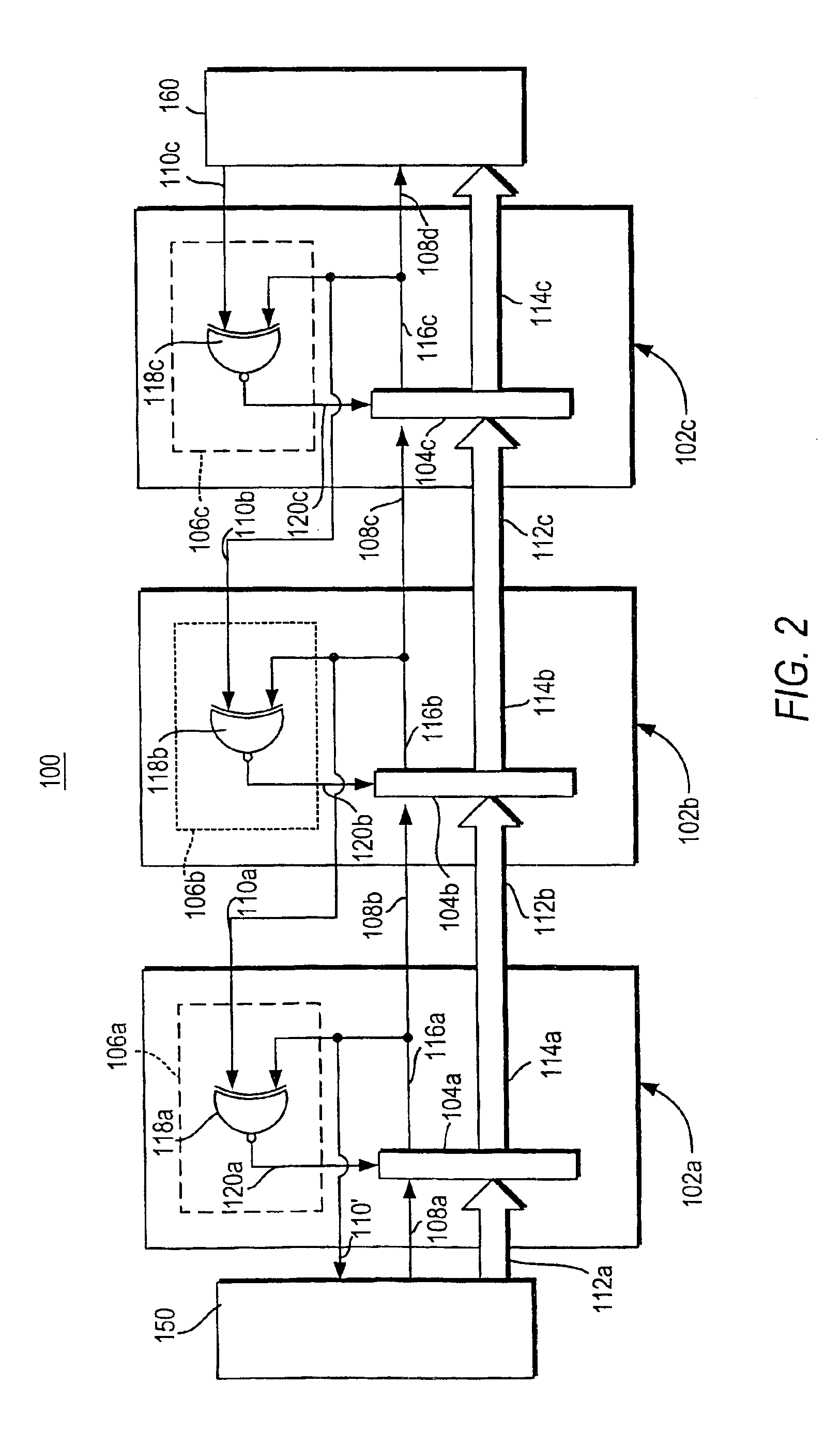
[0095]Simulations were carried out for several of the pipeline styles described herein, using HSPICE, for a basic pipeline, such as pipeline 100, above. A simple 10-stage FIFO was simulated (with no logic processing) on a 16-bit wide datapath. The FIFO was designed and simulated in two different CMOS technologies: (i) a Taiwan Semiconductor Manufacturing Company (TSMC) 0.25 micron CMOS process, which is well-known in the art, and (ii) a 0.6 μm Hewlett-Packard (HP) CMOS14TB process, which is also well-known in the art. For the first technology, only the unoptimized pipeline style was used: we did not include the “waveform shaping” optimization described above. For the second technology, both the optimized and the unoptimized versions of the pipeline were simulated. In each case, careful transistor sizing was used to improve performance.

[0096]The first simulation, using the 0.25 μm TSMC process, was performed assuming a 2.5V power supply, 300K temperature, and a normal process corner ...


PUM


Abstract

An asynchronous pipeline for high-speed applications uses simple transparent latches in its datapath and small latch controllers for each pipeline stage. The stages communicate with each other using request signals and acknowledgment signals. Each transition on the request signal indicates the arrival of a distinct new data item. Each stage comprises a data latch that is normally enabled to allow data to pass through, and a latch controller that enables and disables the data latch. The request signal and the data are inputs to the data latch. Once the stage has latched the data, a done signal is produced, which is sent to the latch controller, to the previous stage as an acknowledgment signal, and to the next stage as a request signal. The latch controller disables the latch upon receipt of the done signal, and re-enables the data latch upon receipt of the acknowledgment signal from the next stage. For correct operation, the request signal must arrive at the stage after the data inputs have stabilized. The asynchronous pipeline may incorporate logic elements to combine data, as well as matched delay elements for the request, acknowledgment, and done signals. The asynchronous pipeline may also incorporate clocked CMOS logic gates. Fork and join structures are also provided by the asynchronous pipeline design.

Description

CROSS-REFERENCE TO RELATED APPLICATION[0001]This application claims the benefit under 35 U.S.C §365 of international Application PCT / US01 / 29721, filed Sep. 21, 2001; and which claims benefit to U.S. Provisional Patent Application entitled “Mousetrap: A High-Throughput Asynchronous Pipeline Style Using a Transition-Signaling Protocol,” Ser. No. 60 / 242,587, which was filed on Oct. 23, 2000, which is incorporated by reference in its entirety herein.STATEMENT OF GOVERNMENT RIGHT[0002]The present invention was made in part with support from U.S. National Science Foundation (NSF), grant no. CCR-97-34803. Accordingly, the U.S. Government may have certain rights to this invention.BACKGROUND OF THE INVENTION[0003]1. Field of the Invention[0004]This invention relates to asynchronous pipelines, and more particularly to asynchronous pipelines for high-speed applications which uses blocks of static logic for processing data, and simple transparent latches to separate data items.[0005]2. Backgrou...

Claims


Application Information

Patent Timeline
Patent Type & Authority Patents(United States)
IPC IPC(8): H03K19/00G06F9/38
CPCG06F9/3869G06F9/3871G06F9/38
Inventor SINGH, MONTEKNOWICK, STEVEN M.
Owner THE TRUSTEES OF COLUMBIA UNIV IN THE CITY OF NEW YORK
Why Eureka
Try Eureka