
Display device, method for driving the same, and portable terminal apparatus using the same

Active Publication Date: 2005-10-25
JAPAN DISPLAY WEST
View PDF4 Cites 7 Cited by
  • Summary
  • Abstract
  • Description
  • Claims
  • Application Information

AI Technical Summary

Benefits of technology

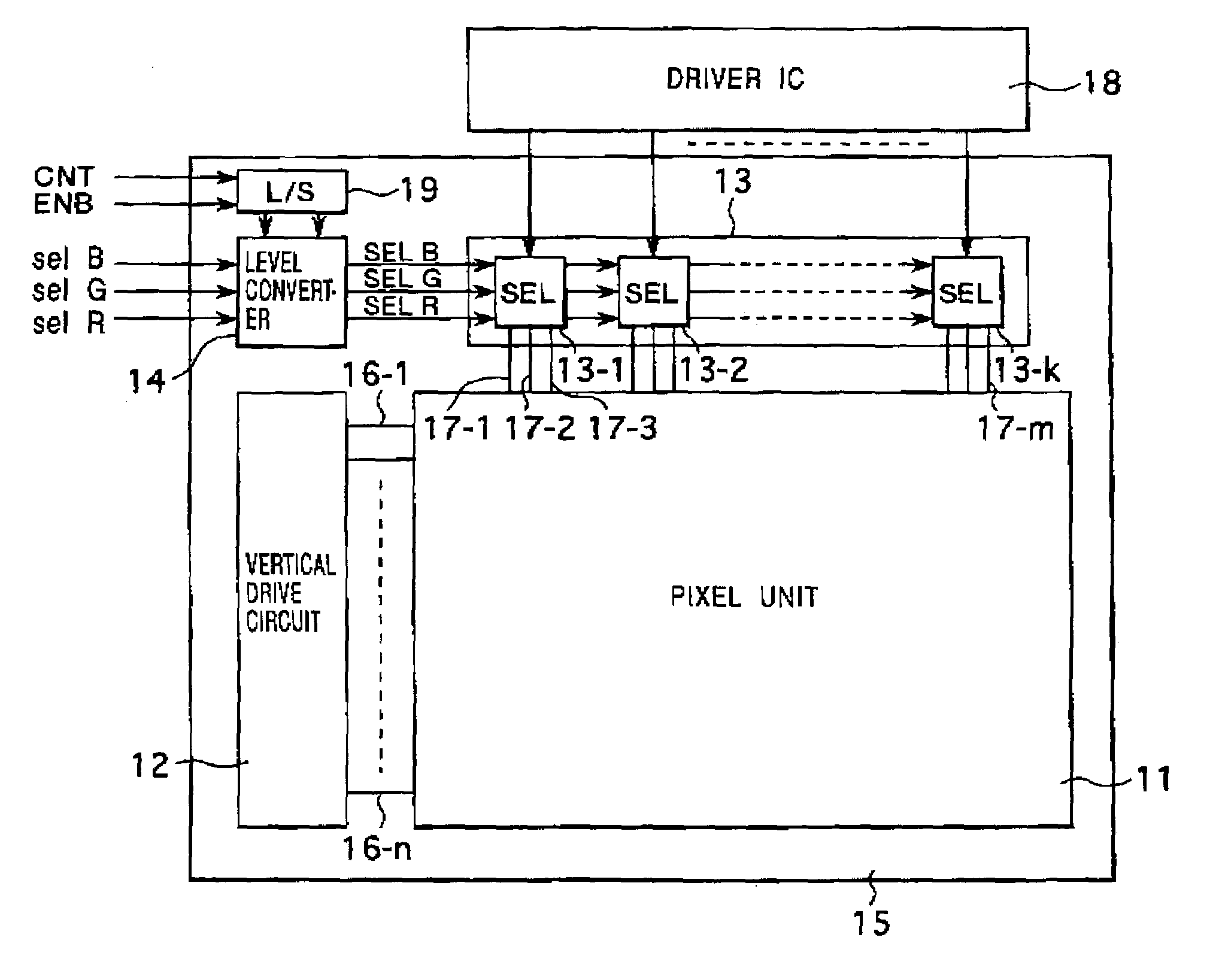
[0012]Accordingly, it is an object of the present invention to provide a display device, a method for driving the same, and a portable terminal apparatus using the same as a display that achieves low power consumption of the entire apparatus by reducing the power consumed by a direct current, particularly in the level converter, when a selector addressing method is employed.
[0016]In the display device and the portable terminal apparatus provided with the above display device as an output display unit, in partial display mode in which displaying is performed on part of the display screen, single-gradation displaying is performed in the non-display region by providing a display signal of a single gradation, such as a white signal in a normally white type display or a black signal in a normally black type display, to the signal lines. Therefore, each select switch of the selecting unit does not have to repeat selection / non-selection operation and only have to be constantly selected. During partial display mode, in the non-display region, the level converting unit is deactivated, and each select switch is set to be constantly selected. This can reduce direct current consumption in the level converting unit compared to when the level converting unit is constantly activated. Hence, direct current consumption in the entire apparatus can be reduced as well.

Problems solved by technology

However, wasteful D.C. consumption occurs in the liquid crystal display with the above selector addressing method because the level converter that level-shits the selector pulse for the external-circuit power voltage to the one for the internal-circuit power voltage is constantly maintained in the ON state.
When the liquid crystal display is applied, in particular, to portable terminal apparatuses such as portable telephones and PDAs, lower power consumption of the display device, such as a liquid crystal display, is a very important issue for realizing further reduced power consumption in the portable terminal apparatus.

Method used


Image

  • Display device, method for driving the same, and portable terminal apparatus using the same
  • Display device, method for driving the same, and portable terminal apparatus using the same
  • Display device, method for driving the same, and portable terminal apparatus using the same

Examples


Embodiment Construction

[0025]FIG. 1 shows a block diagram of the entire construction of a display device, such as a liquid crystal display using a liquid crystal cell as a display element of a pixel, according to one embodiment of the present invention.

[0026]In FIG. 1, the liquid crystal display includes a pixel unit 11, a vertical drive circuit 12, a selection circuit 13, and a level converter 14. The pixel unit 11 includes pixels, each with a liquid crystal cell, disposed in a matrix. The vertical drive circuit 12 selectively drives each pixel of the pixel unit 11 in groups of lines. The selection circuit 13 selectively provides a display signal to pixels of the line driven by the vertical drive circuit 12 by means of the selector addressing method. The level converter 14 level shifts a selector pulse for selectively driving the selection circuit 13.

[0027]The liquid crystal display has a built-in drive-circuit construction in which the vertical drive circuit 12, the selection circuit 13, and the level c...


PUM


Abstract

A selection-addressing-type liquid crystal display selectively addresses a signal line of a pixel unit using groups of three selectors of a selector circuit in a time-division manner. A level converter level shifts selector pulses having a voltage swing corresponding to the external-circuit power supply to selector pulses having a voltage swing corresponding to the internal-circuit power supply. In a non-display region in partial display mode, the level converter is deactivated under the control of a control signal to reduce direct current consumption therein.

Description

[0001]This application claims priority to Japanese Patent Application Number JP2002-130252 filed May 2, 2002 which is incorporated herein by reference.BACKGROUND OF THE INVENTION[0002]1. Field of the Invention[0003]The present invention relates to display devices, methods for driving the same, and portable terminal apparatuses using the same. More particularly, the present invention relates to a display device employing a selector circuit addressing method for driving the signal lines of a display panel, a method for driving the same, and a portable terminal apparatus provided with the same as a display unit.[0004]2. Description of the Related Art[0005]Display devices having pixels disposed in a matrix include a liquid crystal display using a liquid crystal cell as the pixel. The liquid crystal display employs the passive matrix system or the active matrix system as the driving method. Recently, for its improved response characteristics and visibility characteristics, most liquid cr...

Claims


Application Information

Patent Timeline
IPC IPC(8): G09G3/36G02F1/133G02F1/1345G02F1/1368G09G3/20G09G3/30
CPCG09G3/3648G09G2310/0232G09G2330/021G09G2310/0297G09G2310/0289G09G3/36
Inventor MURASE, MASAKINAKAJIMA, YOSHIHARU
Owner JAPAN DISPLAY WEST
Learn More