Engine control based on flow rate and pressure for hydraulic hybrid vehicle

a technology of engine control and hybrid vehicles, applied in hybrid vehicles, fluid couplings, piston pumps, etc., can solve the problems of limiting this gain, customers may perceive cycling as noise vibration or harshness, and achieve the effect of increasing fuel economy and increasing cycling activity

Inactive Publication Date: 2005-11-01
FORD GLOBAL TECH LLC
View PDF7 Cites 31 Cited by
  • Summary
  • Abstract
  • Description
  • Claims
  • Application Information

AI Technical Summary

Benefits of technology

[0007]A system according to this invention controls pressure to a target pressure by deciding when to turn on and off the engine by using system fluid flow rate requirements as a basis for pressure control. The control the flow rate requirements with reference to three flow devices. The primary flow is the flow use by the pump / motors. A second flow produced by the engine-pump assemblies restores target pressure within a given time period. This time period defines a flow rate or gain. The higher this gain, the closer the pressure levels are to target pressure, thus increasing fuel economy. There is a limit to this gain caused by the cost of starting the engine. Also, increasing the target gain will increase cycling activity, and customers may perceive cycling as noise vibration or harshness. The final source of flow is the accumulator storage limits. If the accumulator pressure approaches the minimum operating pressure, the flow requirement is added to insure pressures above the allowable minimum. If the accumulator pressure is close to the maximum pressure, flow is subtracted to insure that overpressure of the system is avoided.
[0010]An advantage of this invention is defining both an explicit cycling range control and an implicit cycling range control in which target pressure is implicit and need not be defined, although its definition may be desired to optimize fuel economy.

Problems solved by technology

There is a limit to this gain caused by the cost of starting the engine.
Also, increasing the target gain will increase cycling activity, and customers may perceive cycling as noise vibration or harshness.

Method used


Image

  • Engine control based on flow rate and pressure for hydraulic hybrid vehicle
  • Engine control based on flow rate and pressure for hydraulic hybrid vehicle
  • Engine control based on flow rate and pressure for hydraulic hybrid vehicle

Examples


Embodiment Construction

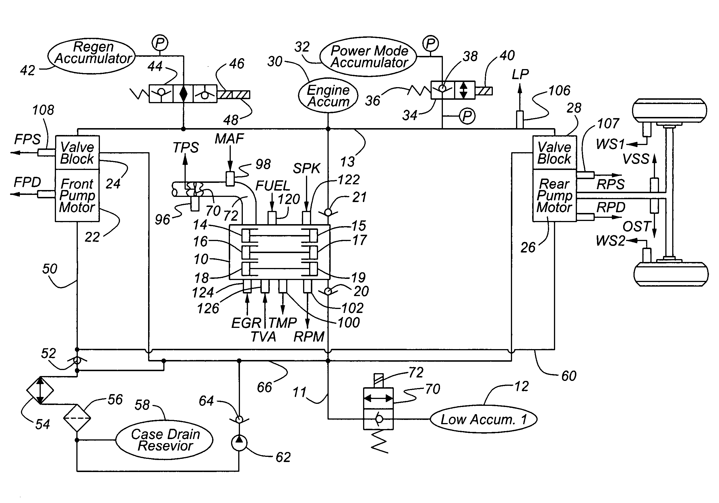
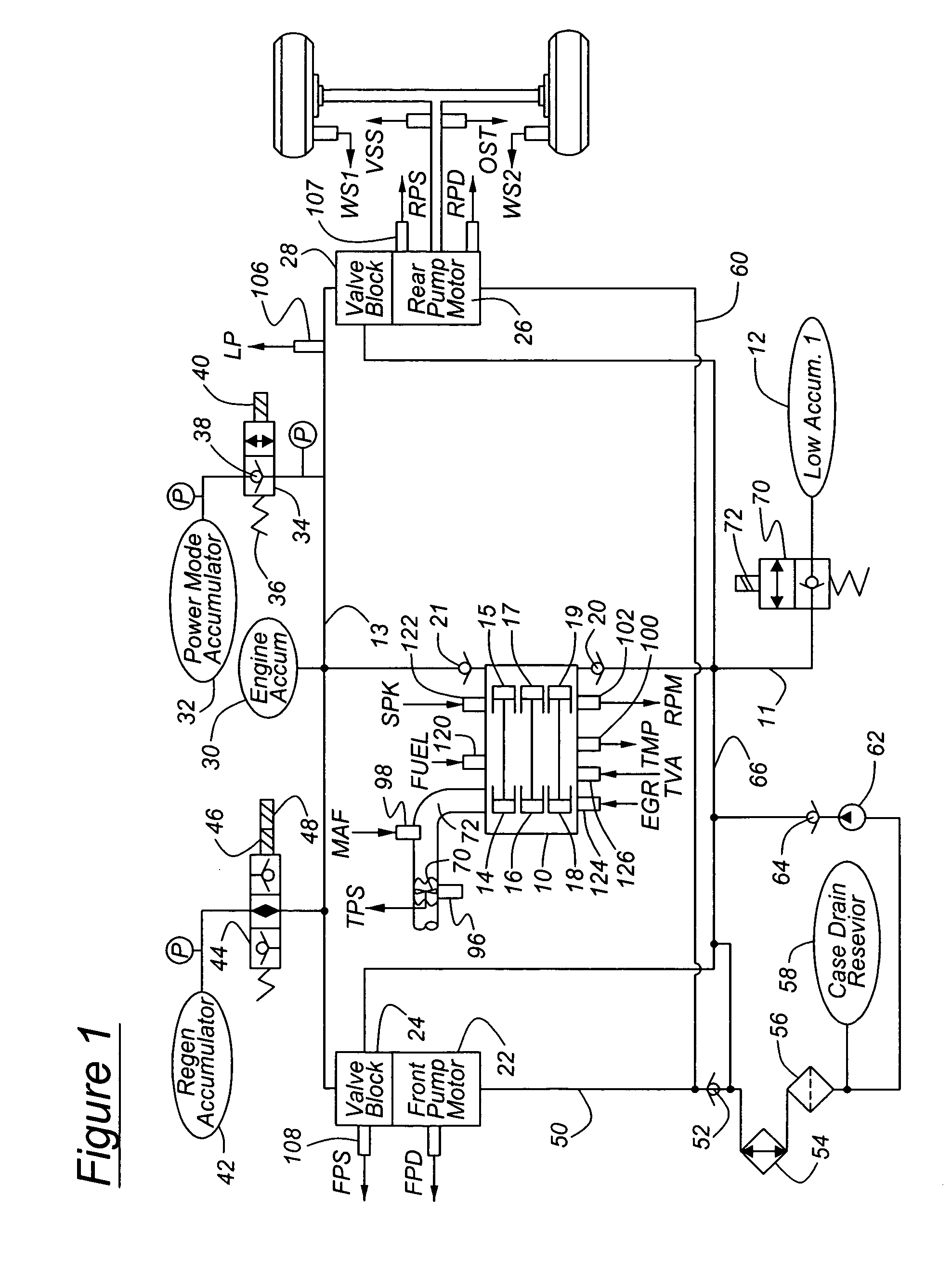
[0017]Referring now to the system illustrated in FIG. 1, a free piston 10 pumps hydraulic fluid from a low pressure line 11, hydraulically connected to a low-pressure accumulator 12, to a high pressure line or rail 13. The engine 10 is divided into multiple banks of cylinders 14, 16. 18, each cylinder driveably connected to a hydraulic pump 15, 17, 19. Check valves 20 are located in the fluid path between low-pressure line 11 and inlet of each pump 15, 17, 19. Check valves 21 are located in the fluid path between high pressure line 13 and outlet of each pump. High pressure rail 13 is connected to a front pump / motor 22 and a rear pump / motor 26 so that they are supplied with pressure at substantially the same magnitude. The flow produced by engine 10 is directly proportional to the number of cylinders and the engine speed. Therefore, power output by the engine is closely related to line pressure, the pressure in rail 13.

[0018]A front hydraulic pump motor 22 is supplied with relatively...


PUM


Abstract

A system for a hydraulically driven vehicle includes an engine having multiple, selectively operating cylinder-pump banks producing fluid flow at an outlet, a pump / motor having a variable flow rate including an inlet for driving the wheels, a hydraulic line having a line pressure and connecting the outlet and the inlet, sensors producing signal representing line pressure, pump / motor speed, pump / motor displacement, and a controller for determining a target hydraulic system parameter, determining, based at least in part on the flow rate of the pump / motor and a flow rate produced by each engine cylinder bank, a number of operating cylinder-pump banks that is required to produce the target hydraulic system parameter, and in response to determining the required number of operating cylinder-pump banks, adjusting an engine operating parameter of a cylinder-pump bank such that the required number of cylinder-pump banks operate.

Description

BACKGROUND OF THE INVENTION[0001]This invention relates to hybrid motor vehicles having several power sources including an internal combustion engine and hydraulic pressure. More particularly, the invention pertains to the control of the engine and line pressure for such vehicles.[0002]A hydraulic hybrid powertrain consisting of a number of free piston engine-pump banks, an accumulator containing hydraulic fluid at relatively high pressure, and pump / motors located at each axle for driving the wheels.[0003]In such a system, there is a mismatch in operating efficiency of the free piston engine-pump and the efficiency of the pump / motors. The assembly that includes a free piston engine driving a hydraulic pump has a higher efficiency at higher pressures. The pump / motors have higher efficiencies at lower pressures. There is an optimum efficiency point where the combined efficiencies of these components produce overall vehicle efficiency. The flow rate produced by the engine is directly p...

Claims


Application Information

Patent Timeline
Patent Type & Authority Patents(United States)
IPC IPC(8): F04B49/08F16D31/02B60K6/12
CPCB60K6/12B60K41/162B60K2741/165Y02T10/6208B60W10/06B60W10/08B60W20/00B60W2710/0605B60W2710/0622B60W2710/0633Y02T10/62
Inventor LIPPERT, ROBERTWILBUR, JR., DON
Owner FORD GLOBAL TECH LLC
Why Eureka
Try Eureka