[0014]It is, therefore, an object of the present invention to provide a hydraulic booster brake system which can supply a hydraulic fluid to both a brake booster and a power steering booster. It is another object of the present invention to provide a hydraulic booster brake system which can set a maximum
working pressure of a brake booster without being subject to a restriction in temperature of a hydraulic fluid.
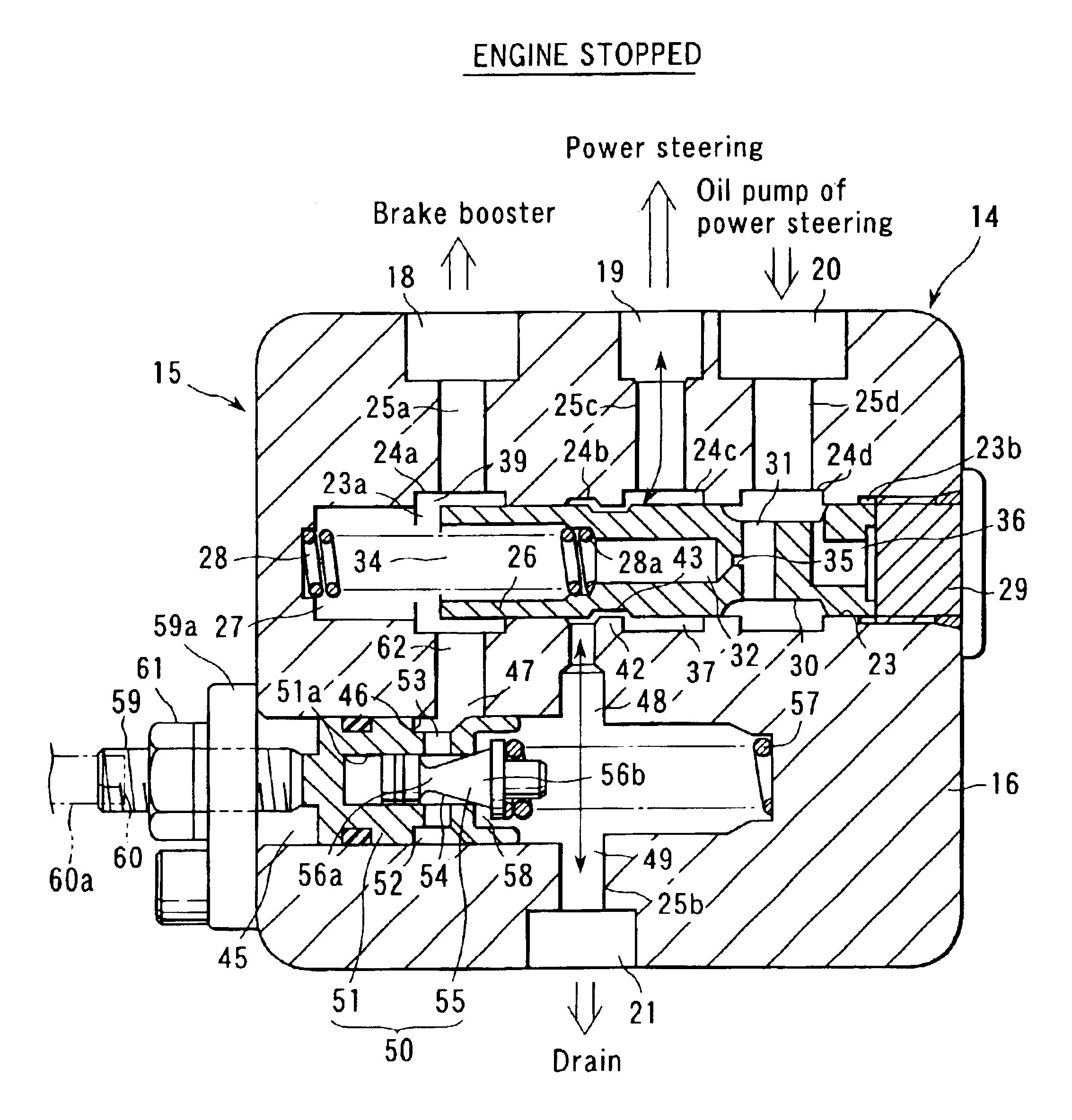
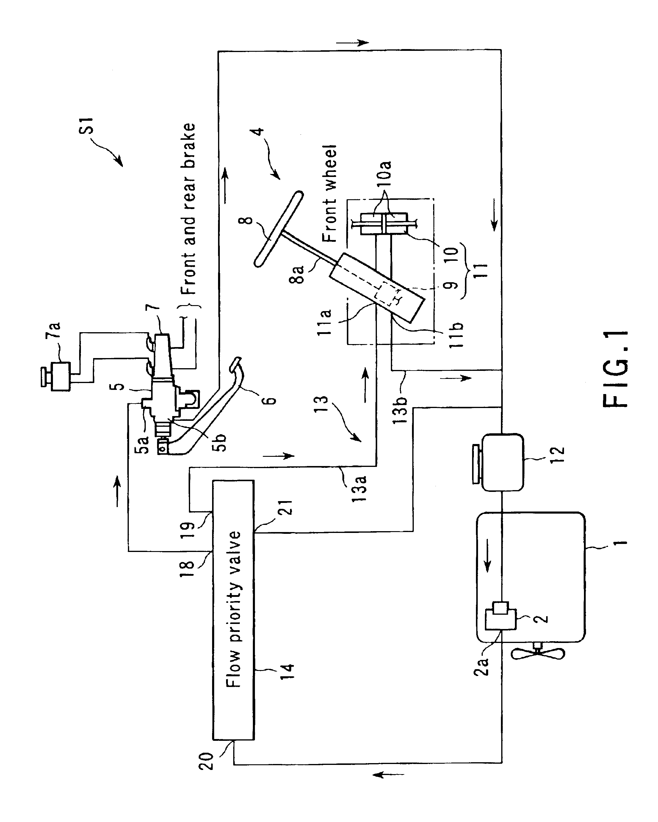
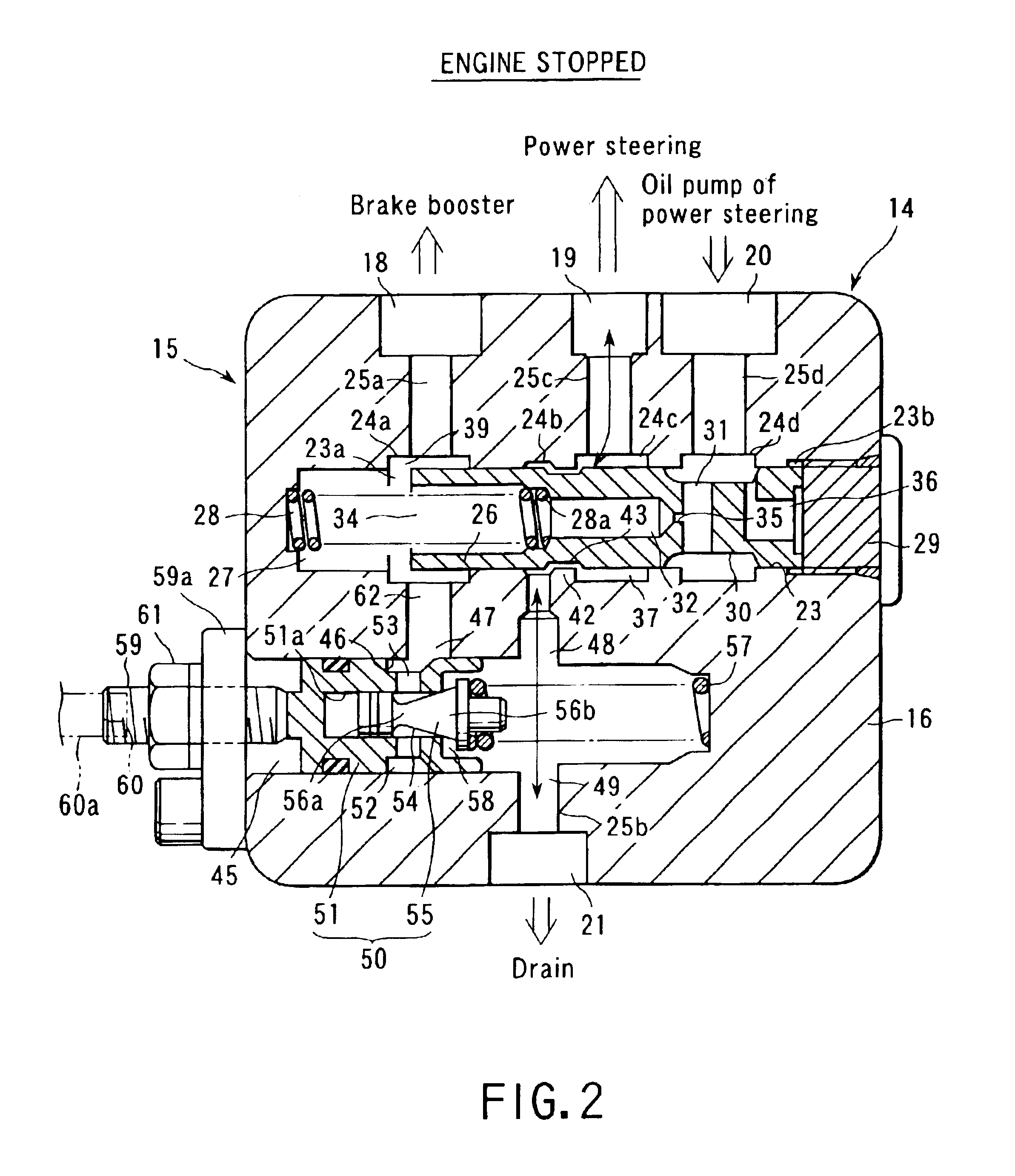
[0017]In the preferred mode according to the present invention, as an example of the flow priority valve, there is employed a
spool valve which can distribute a stipulated quantity of flow with a simple structure. For example, a cylinder of the
spool valve has a first port communicating with a
discharge side of the hydraulic pump, a second port communicating with an inlet side of the power steering booster, and a third port communicating with an inlet side of the brake booster. The spool is accommodated in the cylinder so as to be capable of moving in the axial direction of the cylinder. The spool is pressed in one direction by an urging member, and has a receiving port which receives a pressure of the hydraulic fluid flowing therein from the first port. The
spool valve has an orifice through which the hydraulic fluid from the receiving port passes, a brake booster passage which leads the hydraulic fluid passing through the orifice to the third port, a power steering passage which leads the excessive hydraulic fluid which does not pass through the orifice to the second port from the upstream side of the orifice through a part between an outer
peripheral surface of the spool and an inner surface of the cylinder, a first
choke portion which is formed in the brake booster passage and narrows this passage by using the spool which moves when a pressure of the power steering booster is increased, and a second
choke portion which is formed in the power steering passage and narrows this passage by using the spool which moves when a pressure of the brake booster is increased. According to this structure, the first and second
choke portions are controlled by the spool which moves in accordance with pressures of the power steering booster and the brake booster, and leakage of the hydraulic fluid from a side with a
high pressure to a side with a low pressure can be suppressed. As a result, a stipulated quantity of flow is assured in the brake booster by priority through the third port, and the excessive hydraulic fluid is distributed to the power steering booster through the second port.
[0019]In a hydraulic booster brake system according to the present invention based on another aspect, a
relief valve capable of adjusting a relief pressure is provided between an inlet side of the brake booster and a drain side of the power steering
hydraulic circuit. Adjusting the relief pressure of the relief valve can set a maximum
working pressure of the brake booster.
[0020]According to this structure, when the brake booster reaches the maximum working pressure, the relief valve is opened. Therefore, the hydraulic fluid can be supplied to the brake booster and the power steering booster, whilst the excessive pressure can be passed to the drain side. As described above, with the structure that the maximum working pressure of the brake booster is set in accordance with the relief pressure of the relief valve, it is possible to suppress irregularities in maximum working pressure due to a temperature or the like of the hydraulic fluid. Further, a stipulated quantity of flow can be assured in each of the brake booster and the power steering booster, and the maximum working pressure of the brake booster can be set to a high value close to the maximum working pressure of the power steering booster.
[0021]Therefore, the maximum working pressure of the brake booster can be increased, thereby improving the brake performance. Furthermore, the hydraulic fluid is supplied to the brake booster with the great importance by priority.
[0023]The preferred mode of the relief valve includes a valve chest which has an inlet port communicating with a passage on the downstream side from the first choke portion and an output port communicating with the drain side of the power steering
hydraulic circuit. Moreover, this relief valve includes a valve body which moves to a position at which the inlet port is caused to communicate with the outlet port when an excessive pressure is applied from the inlet port, an urging member which presses the valve body in a closing direction, and a relief pressure adjusting member which adjusts an urging force of the urging member. This relief valve has a simple structure, but can smoothly move and set the maximum working pressure.

