Gasifier system and method

a gasifier and gas technology, applied in the field of gasifier systems and methods, can solve the problems of reducing the quantity of carbon monoxide produced and the energy required to move, and achieve the effect of minimizing the heat loss of unnecessary heating air

Inactive Publication Date: 2005-11-01
MUNIZ CESAR A
View PDF18 Cites 12 Cited by
  • Summary
  • Abstract
  • Description
  • Claims
  • Application Information

AI Technical Summary

Benefits of technology

[0004]According to the present invention, firebelts ensure that the heat loss from heating unnecessary air is minimized. The quantity o

Problems solved by technology

First, by minimizing the heat loss of the combustion process, this minimizes the amount of carbon monoxide which is produced. Carbon monoxide, a priority pollutant, is produced directly proportional to the combustion temperature. Therefore, by minimizing excess air, the quantity of carbon monoxide produced is minimized.
Secondly, nitrogen oxides, another priority pollutant, is produced by combining the nitrogen in the air with the oxygen in the air. This combination of nitrogen and oxygen only occurs at high temperatures. The higher the temperature, the greater the quanti

Method used


Image

  • Gasifier system and method
  • Gasifier system and method
  • Gasifier system and method

Examples


Embodiment Construction

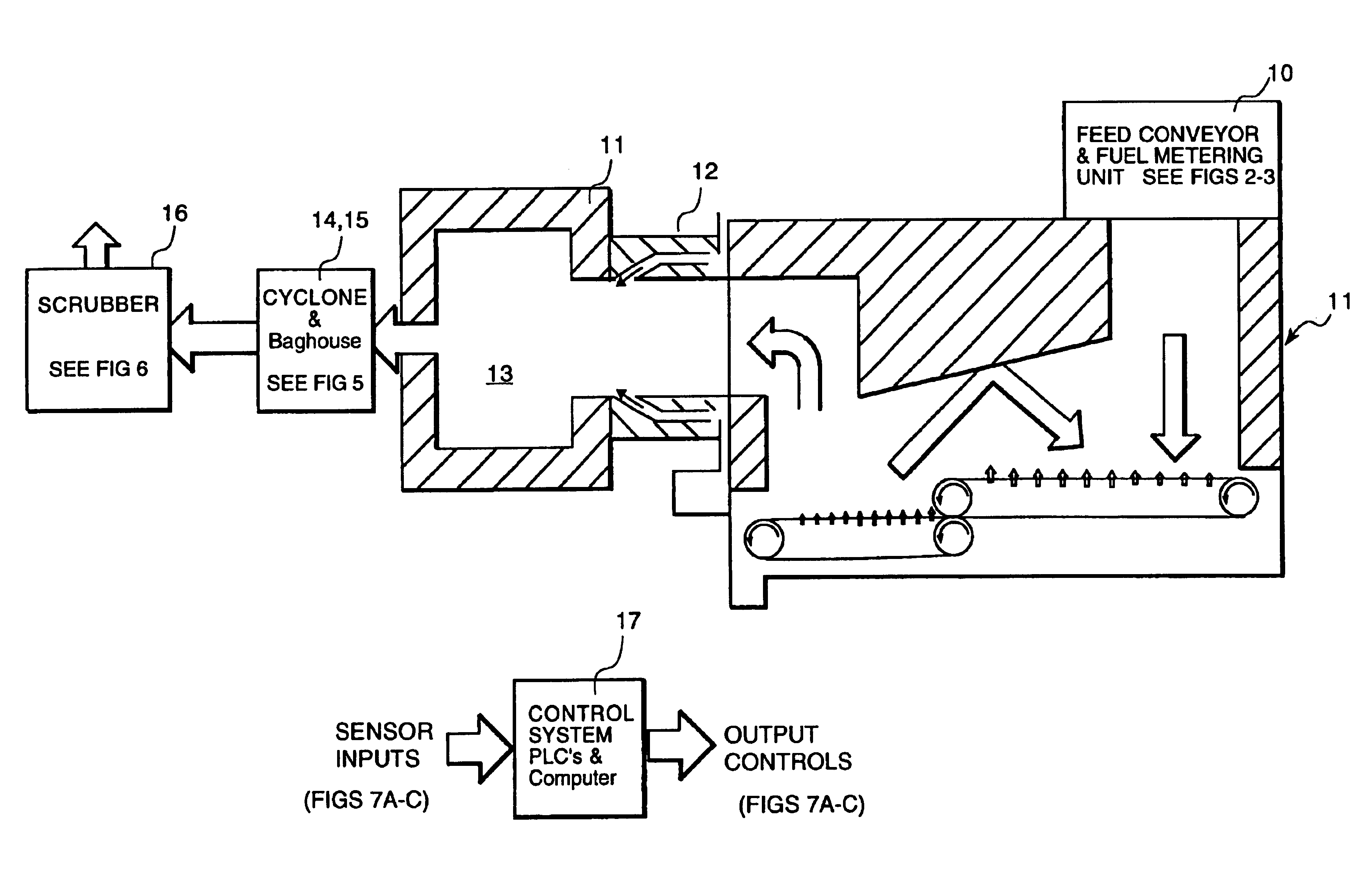
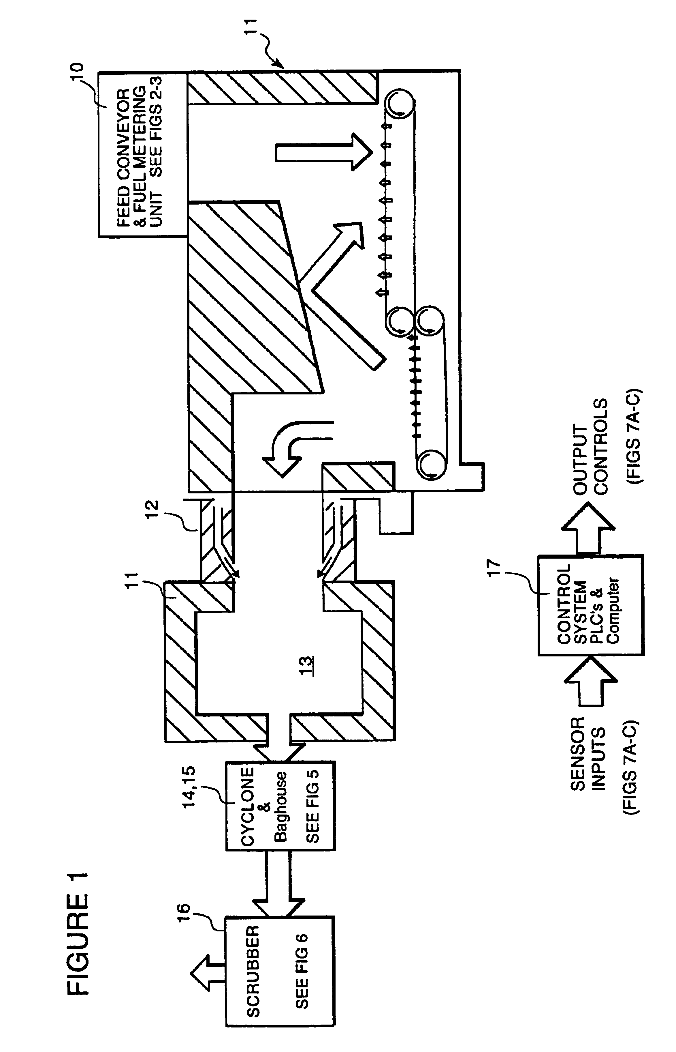
[0023]Referring now to FIG. 1, the gasifier system comprises an inlet feed conveyor and fuel metering unit 10, a gasifier 11, a gasifier firetube with connection to boiler 12, the boiler itself 13, a cyclone 14, baghouse 15, scrubber 16, and computer control system 17 which computer control system is diagrammatically illustrated in FIGS. 7A, 7B and 7C.

Inlet Feed Conveyor With Fuel Metering Unit 10

[0024]This section delivers the prepared fuel to the gasifier. It includes the bin conveyor and rotary airlock. The computer control system determines the required fuel flow for proper gasification and the quantity to sustain the output of steam from the boiler. It then determines the required speed of the conveyor and the airlock.

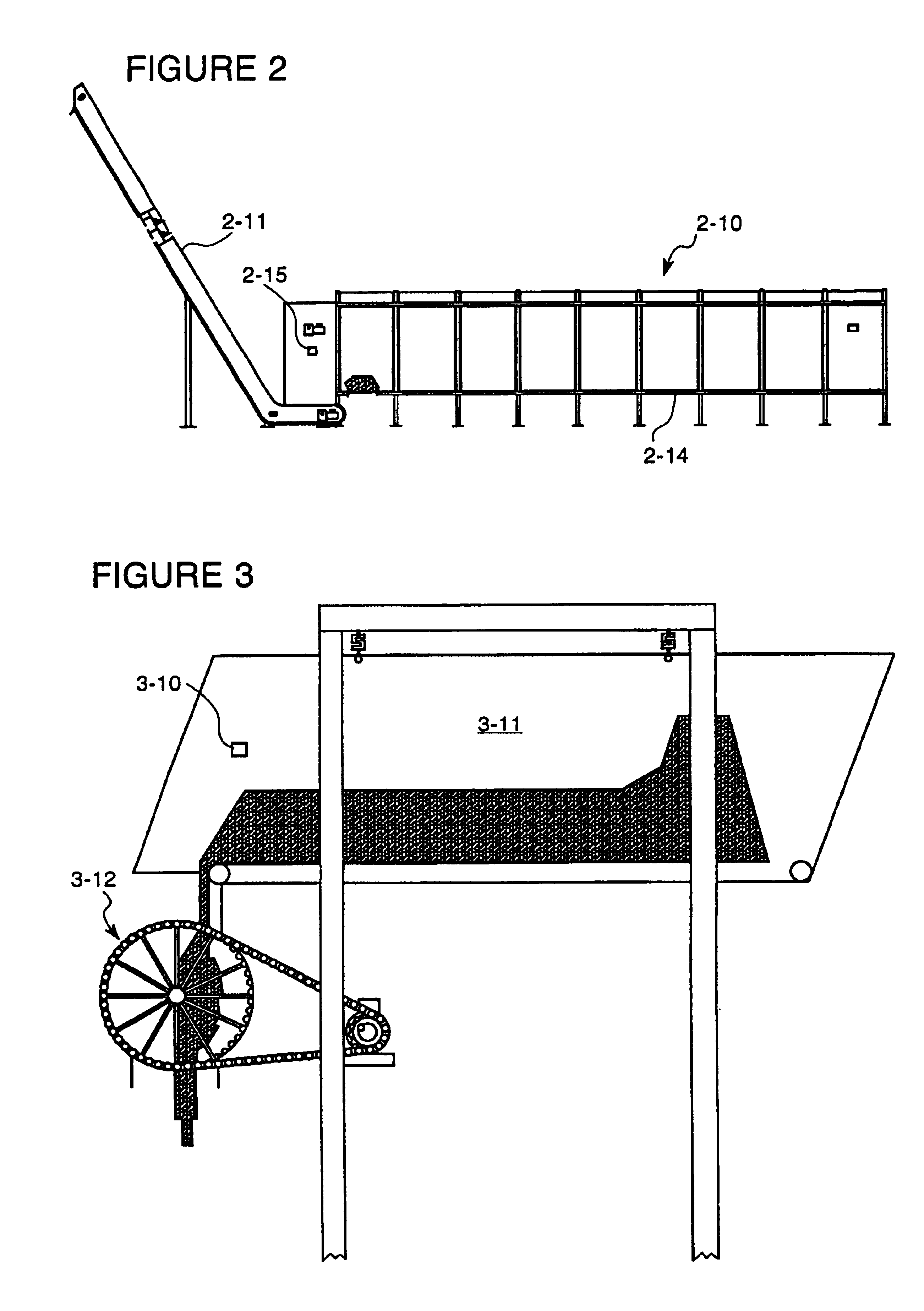
Walking Floor Trailer and Inclined Conveyor (FIG. 2)

[0025]The walking floor trailer 2-10 is used to store and deliver fuel to the combustor with the inclined conveyor. The bin conveyor 2-12 monitors the amount of fuel and calls for additional fuel from the walking...


PUM


Abstract

A solid fuel fed combustor method having a first chamber portion with an inlet feeding a metered amount of a solid fuel to a first burner stage having a first traveling conveyor firebelt. A metered amount of air is introduced in progressively increasing proportions along the length thereof to cause endothermic reduction of the solid fuel. The first stage feeds a second burner stage having a second traveling conveyor firebelt. Air is introduced in a progressively decreasing amount along the length of the second traveling conveyor firebelt to induce exothermic combustion and decomposition of fuel. The amount of air introduced and speed of the conveyors are controlled to minimize the quantity of carbon monoxide and nitrogen oxides and other pollutants. Radiative energy generated from fuel traveling on the traveling conveyor firebelts is reflected on fuel traveling on the first firebelt.

Description

REFERENCE TO RELATED APPLICATIONS[0001]This is division of application Ser. No. 10 / 061,362, filed Feb. 4, 2002 now U.S. Pat. No. 6,532,879 which in turn is a continuation of Ser. No. 09 / 138,020, filed Aug. 21, 1998 now abandoned.BACKGROUND AND BRIEF DESCRIPTION OF THE INVENTION[0002]This invention relates to gasifier systems and methods for the efficient conversion of solid fuels to usable heat energy.DESCRIPTION OF THE PRIOR ART[0003]The prior art is best exemplified by U.S. Pat. No. 5,284,103 entitled BIO-MASS BURNER CONSTRUCTION by Hand et al, which is a division of U.S. Pat. No. 5,178,076 entitled BIO-MASS BURNER CONSTRUCTION issued Jan. 12, 1993 to the same inventors. In these patents, the burner utilizes a first burning chamber having a falling fuel entrained bed zone positioned above a traveling grate having a porous metallic woven belt. Primary air is directed through the porous belt to establish an oxygen-starved first burning chamber. A second burning chamber in fluid comm...

Claims


Application Information

Patent Timeline
IPC IPC(8): F23G5/027F23L15/00F23G5/44F23G5/00F23G5/16F23N1/02F23N5/00
CPCF23G5/006F23G5/0276F23G5/16F23G5/444F23L15/00F23G2201/303F23G2203/105F23G2203/8016F23G2205/122F23G2205/18F23G2206/203F23G2900/50006F23J2217/40F23J2217/50F23N1/02F23N5/003F23N2023/02F23N2023/08F23N2037/16Y02E20/12F23N2223/02F23N2223/08F23N2237/16Y02E20/34
Inventor ABRAMS, STAN E.
Owner MUNIZ CESAR A
Why Eureka
Try Eureka