Film formation method, semiconductor element and method thereof, and method of manufacturing a disk-shaped storage medium
a technology of semiconductor elements and film formation methods, which is applied in the manufacture of resistive materials, optical record carriers, metallic material coating processes, etc., can solve the problems of unfavorable environmental effects, uneven film thickness, waste of many solutions, etc., and achieve excellent electric characteristics, improve storage reliability, and improve uniform film thickness.
- Summary
- Abstract
- Description
- Claims
- Application Information
AI Technical Summary
Benefits of technology
Problems solved by technology
Method used
Image
Examples
first embodiment
[0070][First Embodiment]
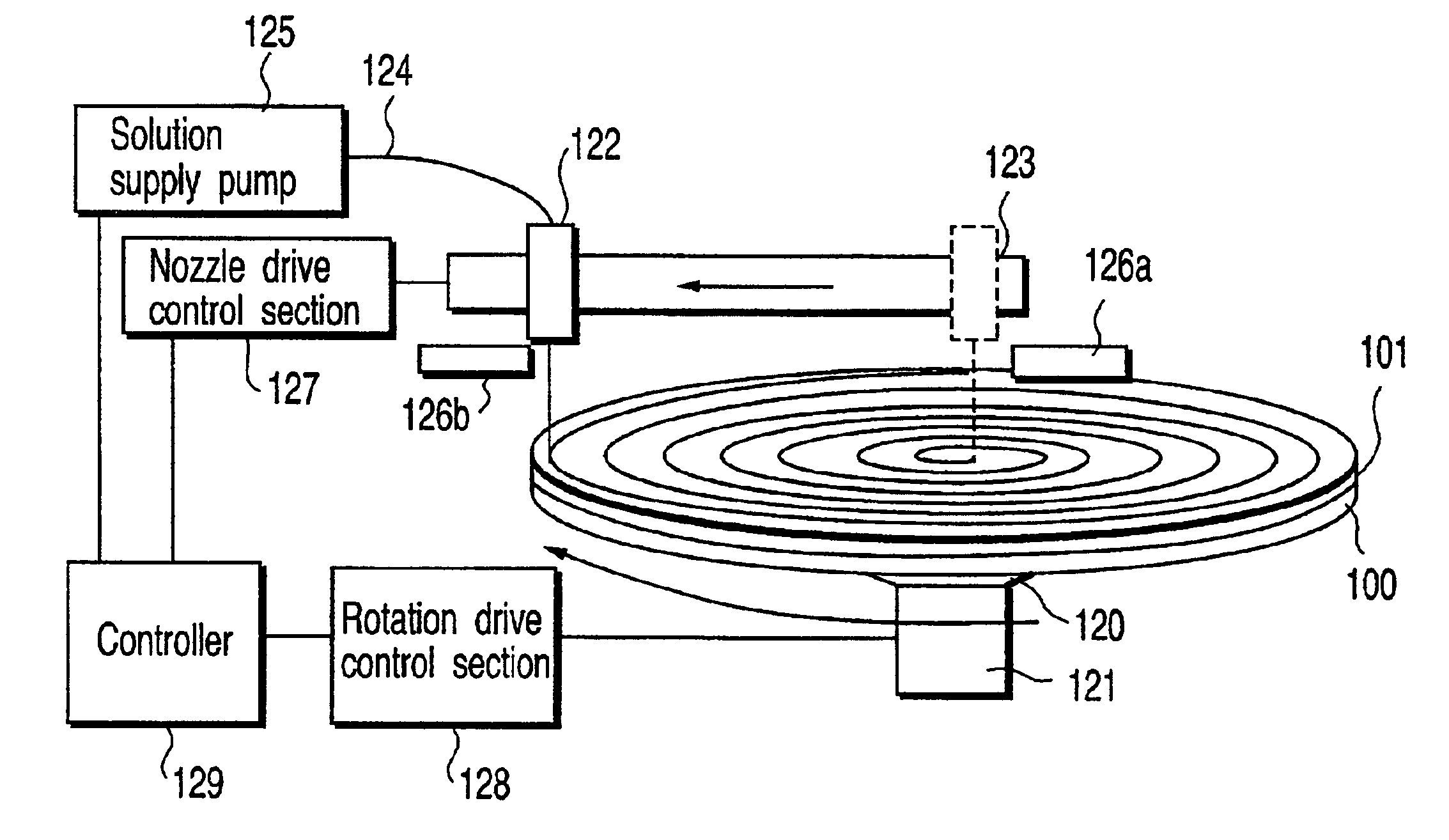
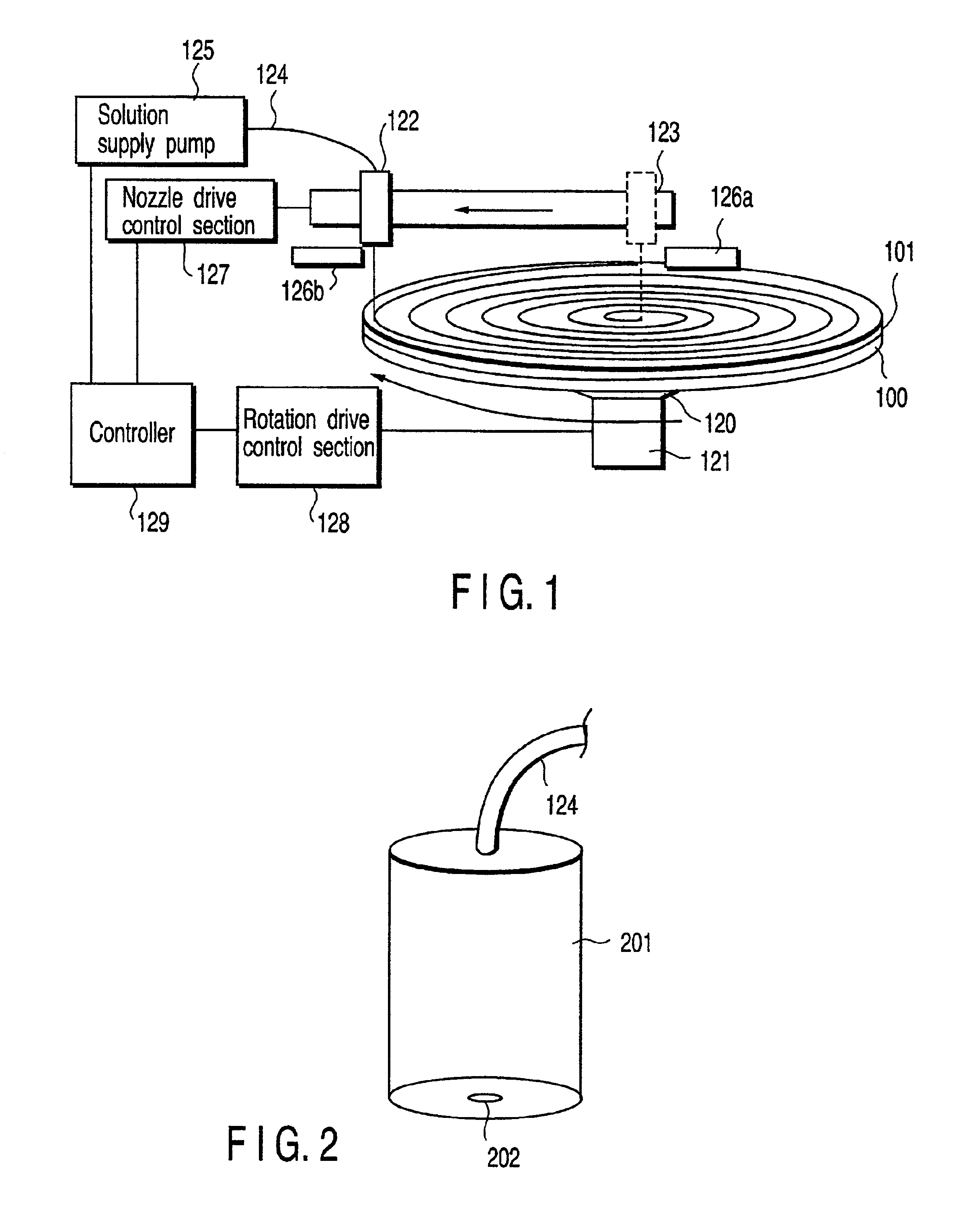
[0071]FIG. 1 is a configuration chart showing a configuration of a film formation apparatus used for the present invention.
[0072]As shown in FIG. 1, an in-process substrate 100 is mounted on a substrate support 120 which is connected to a drive system 121 revolving around a center of the substrate 100. Above the in-process substrate 100, a solution supply nozzle 122 is installed. By discharging solution, the solution supply nozzle 122 is moveable in a diameter direction according to a nozzle drive system 123. The solution supply nozzle 122 is connected to a solution supply pump 125 which supplies the solution supply nozzle 122 with solution via a solution supply pipe 124. Solution discharge from the solution supply nozzle 122 is controlled by controlling a solution supply pressure from a solution supply pump 125.
[0073]FIG. 2 shows a configuration example of the solution supply nozzle 122. As shown in this figure, the solution supply nozzle 122 includes a solu...
second embodiment
[0099][Second Embodiment]
[0100]This embodiment explains a technique for improving a film formation speed.
[0101]For improving the film formation speed, this embodiment, as shown in FIG. 5, uses a nozzle having first and second solution baths 701 and 702 provided with first and second solution discharge openings 704 and 705. These solution baths are separated by a partition plate 703. The first and second solution discharge openings 704 and 705 are arranged along the diameter direction. The first and second solution baths 701 and 702 are supplied with solution from first and second solution supply pipes 706 and 707. The first and second solution supply pipes 706 and 707 are connected to independent solution supply pumps. It is possible to individually control solution discharge speeds from the two solution discharge openings 704 and 705 by independently controlling pressures of the respective solution supply pumps. Since the configuration of the entire apparatus is the same as that in...
third embodiment
[0117][Third Embodiment]
[0118]This embodiment relates to a technique of forming a light absorptive / reactive film for a compact disk recording medium (CD-R) used as a computer storage. This embodiment uses the same film formation apparatus as described for the first embodiment with reference to FIG. 1.
[0119]An in-process substrate is 12 cm in diameter and ensures a region within φ40 mm (radius r=0 to 20 mm) from the center as a holding region where no film is formed. The technique according to the present invention is used to coat a region ranging from the radius r=20 to 60 mm on this substrate with a light absorptive / reactive film.
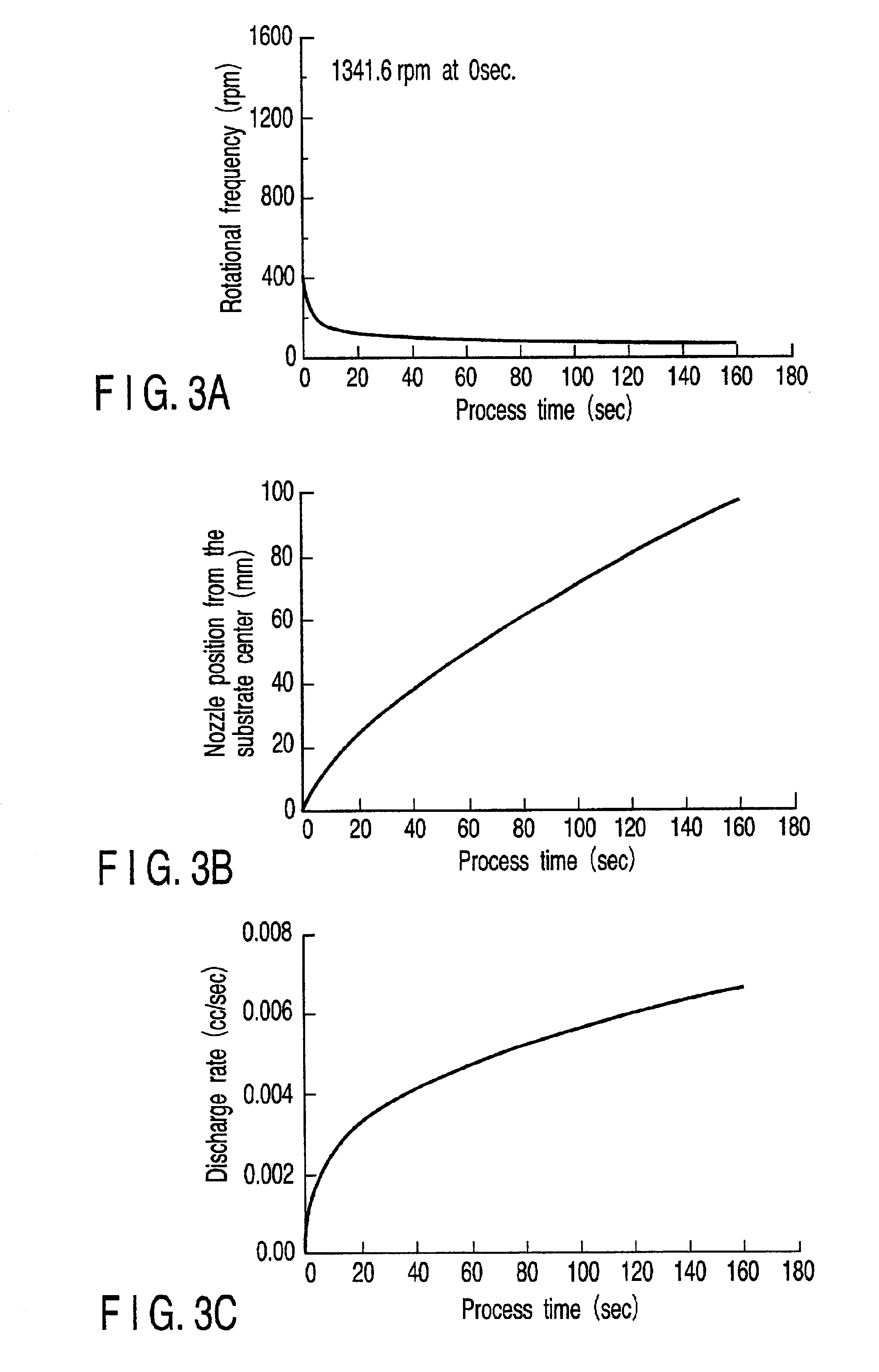
[0120]Relations in FIGS. 10A to 10C are used to control the solution supply nozzle, the in-process substrate rotational frequency, and the solution discharge speed. These relations are stored in the controller in advance. It may be preferable to store these relations in downstream control sections individually. Then the light absorptive / reactive material s...
PUM
| Property | Measurement | Unit |
|---|---|---|
| Diameter | aaaaa | aaaaa |
| Diameter | aaaaa | aaaaa |
| Angular velocity | aaaaa | aaaaa |
Abstract
Description
Claims
Application Information
 - R&D
- Intellectual Property
- Life Sciences
- Materials
- Tech Scout
- Unparalleled Data Quality
- Higher Quality Content
- 60% Fewer Hallucinations
Browse by: Latest US Patents, China's latest patents, Technical Efficacy Thesaurus, Application Domain, Technology Topic, Popular Technical Reports.
© 2025 PatSnap. All rights reserved.Legal|Privacy policy|Modern Slavery Act Transparency Statement|Sitemap|About US| Contact US: help@patsnap.com


