Microcomputer and debugging system

a microcomputer and debugging system technology, applied in the field of microcomputers, can solve the problems of significantly affecting the real-time trace, and becoming more difficult to perform the real-time trace, and achieve the effect of eliminating the overflow of trace information

Inactive Publication Date: 2005-11-01
RENESAS ELECTRONICS CORP
View PDF9 Cites 17 Cited by
  • Summary
  • Abstract
  • Description
  • Claims
  • Application Information

AI Technical Summary

Benefits of technology

[0033]Due to this construction, there is an effect that the microcomputer may be obtained that can eliminate overflow of the trace information without predicting the quantity of the generated trace information and at the same time reconstruct given trace information from each of the trace information collected a plurality of times in a split manner regardless of the number of trace repetition, and therefore collect the trace information without overflow and without need to add the number of trace information output pins or increase operating frequency of the trace clock signal to speed up.

Problems solved by technology

However, there have been appeared various problems with using the debugger comprising the above ICE, as a result of the fact that working frequencies of microcomputers have increased and that, at present, a CPU, a memory element and peripheral feature blocks may be often contained in one chip with advancement of LSI higher integration technology.
More specifically, for example, increase of a working frequency of a microcomputer may cause delay in signal transmission between the ICE main unit and the microcomputer to be evaluated, which may interfere with real-time trace.
In particular, signal delay in a path between the ICE main unit and the microcomputer to be evaluated or in a buffer that stores trace information read out from the microcomputer by the ICE may significantly affect the real-time trace.
Consequently, it becomes more difficult to perform the real-time trace that monitors access by the CPU to an external bus at the clock frequency at which the actual microcomputer runs.
In addition, miniaturization and diversification of microcomputers with advancement of LSI higher integration technology affect prices of probes that connects the ICE main unit to a printed circuit board on which the microcomputer to be evaluated is installed.
Further, by miniaturization of microcomputers, it becomes necessary to use expensive adaptors to connect the above probes, which may cause cost-related problems.
The conventional microcomputer of the above-described construction has such a problem that the trace information may not be output fully in case of successive branches and the like, in other words, a so-called overflow of the trace information may occur, thereby adversely affecting the real-time trace of the program.
However, it is difficult to increase the trace clock (TRCLK) frequency in comparison with acceleration of access of the CPU 104 to the memory-peripheral features block 105, because the trace information is output via the external pin (TRDATA pin).
Further, it may be also contemplated to output the trace information in parallel by using multiple external pins (TRDATA pins), but it is not appropriate because it may increase a cost of the microcomputer 103 and moreover restrict miniaturization of its size.

Method used


Image

  • Microcomputer and debugging system
  • Microcomputer and debugging system
  • Microcomputer and debugging system

Examples


first embodiment

(First Embodiment)

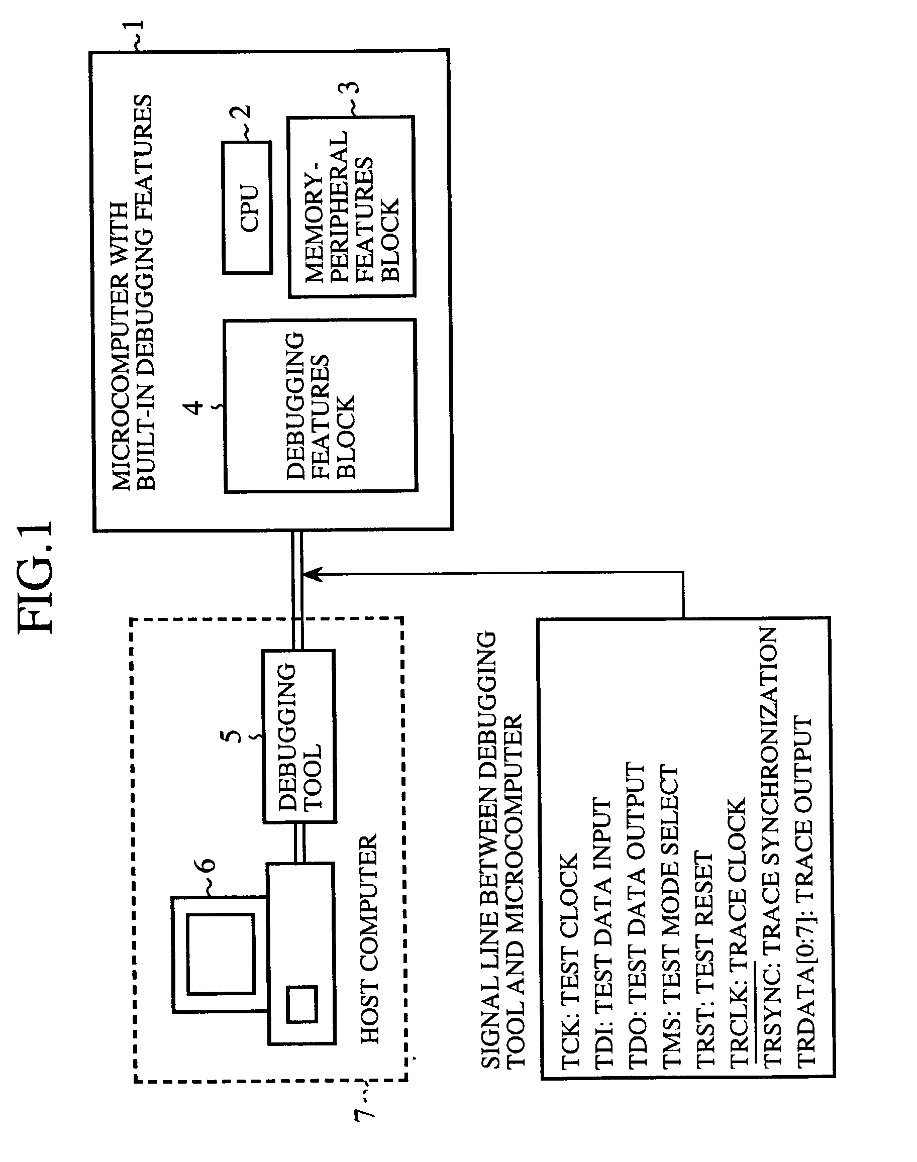
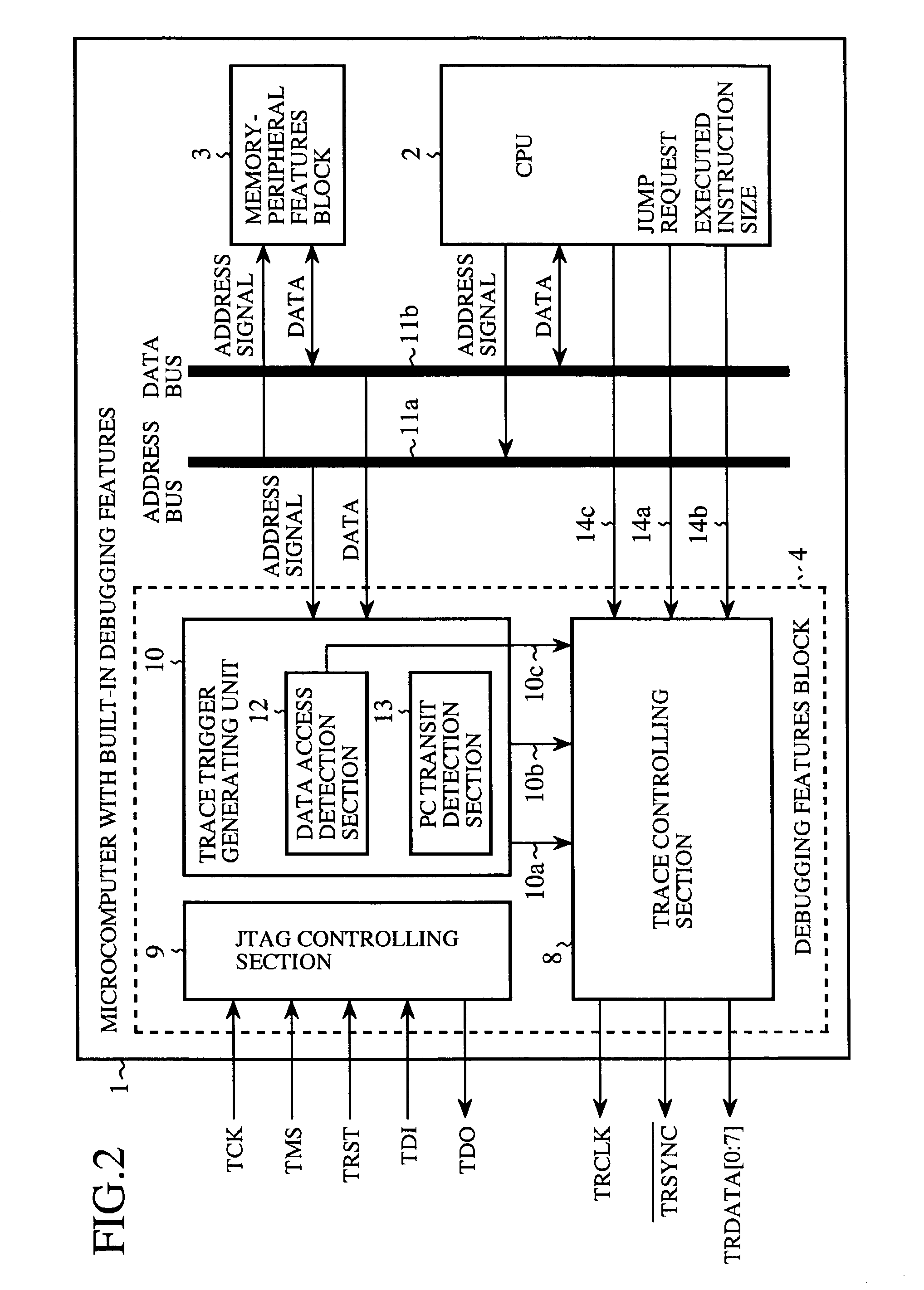
[0051]FIG. 1 is a diagram schematically showing a configuration of a debugging system according to a first embodiment of the present invention. In this figure, a microcomputer with built-in debugging features 1 used in the debugging system according to the first embodiment consists of one chip in which a CPU 2 and a memory-peripheral features block 3 as well as a debugging features block 4 that provides debugging features are formed. The CPU 2 in the microcomputer 1 executes a program to be evaluated that is stored in, for example, the memory-peripheral features block 3. The memory-peripheral features block 3 in the microcomputer 1 includes built-in peripheral I / O such as, for example, a built-in SRAM, a DMA controller, an interrupt controller, a timer and the like. The debugging features block 4 debugs under the control of a debugging tool 5. The debugging tool (debug controlling means) 5 exchanges debug-related information and trace information with the microcomp...

second embodiment

(Second Embodiment)

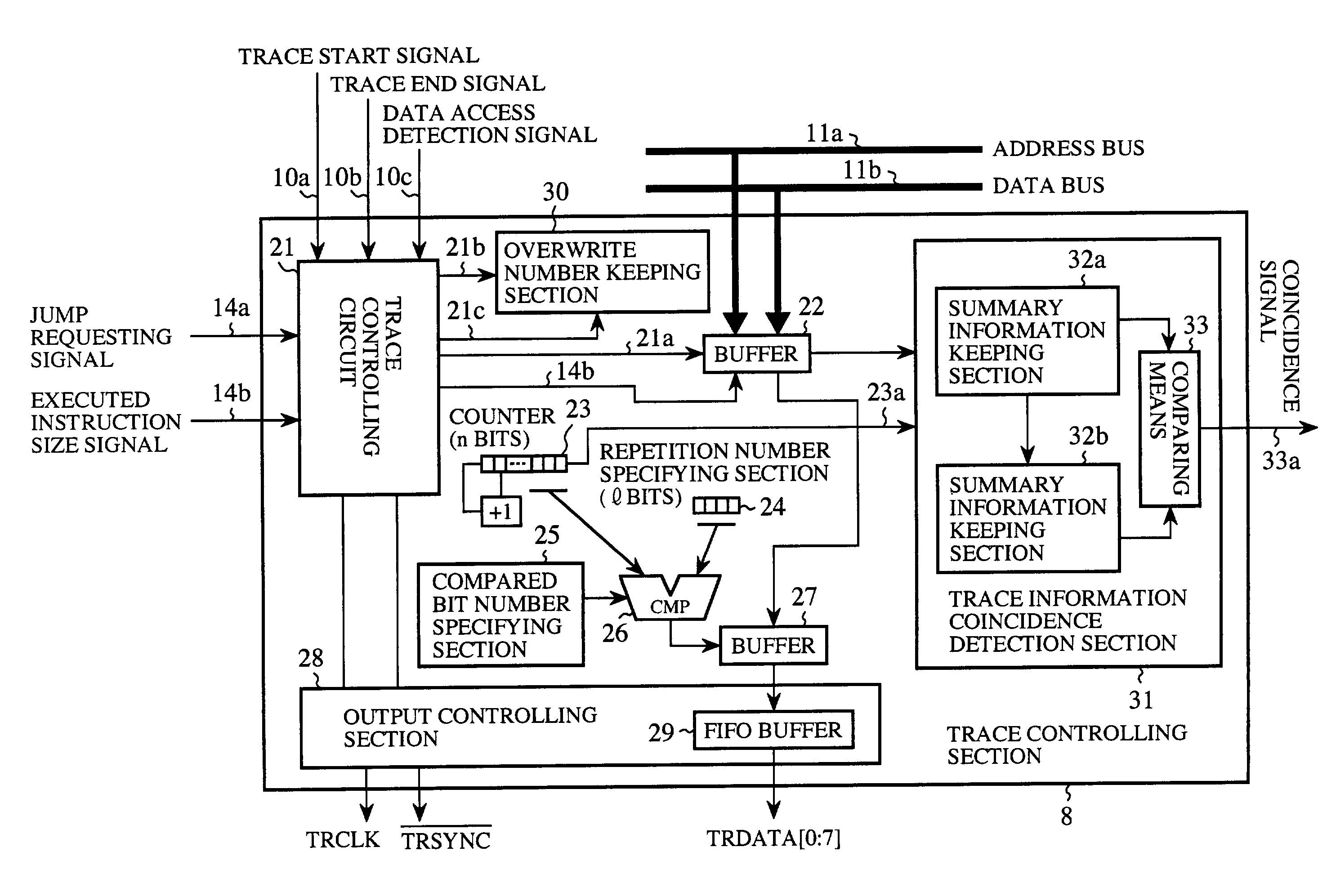
[0101]FIG. 11 is a block diagram showing a trace controlling section of a debugging system according to a second embodiment of the present invention. In this figure, a reset signal 21b is output from the trace controlling circuit 21 to an overwrite number keeping section 30 to reset the content kept in the overwrite number keeping section 30. An overwrite number setting signal 21c is output from the trace controlling circuit 21 to the overwrite number keeping section 30 to indicate the number of the discarded trace information. The overwrite number keeping section 30 (the discard number keeping means) is comprised of a counter that keeps the maximum number of the trace information that is discarded continuously from start to end of acquisition of the trace information. Here, it is to be noted that elements similar to those in FIG. 4 are given like reference numerals and description of these elements is omitted.

[0102]Next, the operation will be described.

[0103]Firs...

third embodiment

(Third Embodiment)

[0127]FIG. 12 is a block diagram showing a trace controlling section of a debugging system according to a third embodiment of the present invention. In this figure, a counter value indicating signal 23a is output from the trace information counter 23 to a trace information coincidence detection section 31 to notify the trace information coincidence detection section 31 of the number of occurrence of the trace information. The trace information coincidence detection section 31 is comprised of summary information keeping section 32a, 32b and a comparing means 33 and detects whether a plurality of the trace information acquired in a split manner coincides or not. Each of the summary information keeping section (the summary keeping means) 32a, 32b keeps summary information about the trace information acquired in a split manner plural times (that consists of a checksum calculated for all of the trace information, a checksum for the address information in the trace infor...


PUM


Abstract

A microcomputer according to the present invention includes: collecting unit for generating and collecting a series of trace information for each execution process of a program to be evaluated in a preset sampling period for a predetermined number of repetitions; outputting circuit for outputting the series of the trace information for each repetition; and decimating circuit for deleting any of the trace information collected at each repetition so that the outputting circuit can output all of the trace information to be collected within the sampling period when the collecting circuit has finished repetitive collection process.

Description

BACKGROUND OF THE INVENTION[0001]1. Field of the Invention[0002]The present invention relates to a microcomputer that is effective for debugging in a real working environment, and more particularly, it relates to a microcomputer that collects trace information at a plurality of times in a debugging operation while decimating it at a predetermined time period as well as a debugging system for controlling the debugging by the microcomputer and a method for collecting such trace information.[0003]2. Description of Related Art[0004]Upon development of a microcomputer system, verification of its operation and debugging of its software may be commonly performed by a so-called debugger, which is a development support device using any debugging tool such as an ICE (In-Circuit Emulator). The ICE comprises features for substituting for a CPU or a program memory to be developed and for debugging programs and hardware efficiently. For example, such features may include a real-time trace feature...

Claims


Application Information

Patent Timeline
Patent Type & Authority Patents(United States)
IPC IPC(8): G06F11/36G06F11/28G06F11/34
CPCG06F11/28G06F11/3636G06F11/3648
Inventor YAMAMOTO, OSAMUIWATA, SHUNICHI
Owner RENESAS ELECTRONICS CORP
Why Eureka
Try Eureka