Controlled method for segmented electrode apparatus and method for plasma processing

a segmented electrode and apparatus technology, applied in the direction of instruments, fluid pressure measurement, coatings, etc., can solve the problems of complex plasma reactor apparatus, complicated electrode and chamber design, and inability to control the plasma to obtain uniform etching and deposition

Inactive Publication Date: 2005-11-08
TOKYO ELECTRON LTD
View PDF11 Cites 57 Cited by
  • Summary
  • Abstract
  • Description
  • Claims
  • Application Information

AI Technical Summary

Problems solved by technology

A problem that has plagued prior art plasma reactors is the control of the plasma to obtain uniform etching and deposition.
The need for multiple gas lines and multiple sets of cooling lines significantly complicates the electrode and chamber design, and makes for a complex plasma reactor apparatus that is more susceptible to failures.
Typically, insulator 710 needs to be cut or otherwise formed into a complex shape, which is expensive and difficult to manufacture.
In addition, insulator 710 is typically fragile and thus prone to breaking because of the small size of the critical dimensions of the insulator.
Even once it has been made, the insulator is prone to cracking because of mechanical stress that builds up at the relatively sharp corners.
However, a shortcoming of the apparatus described in the '511 patent is that the electrode segments are not driven by separate RF power sources, but the λ / 4 cables are all connected to a common point at the match network output, so that there is no means provided for control of individual segments.
Also, according to the Figures in '511 patent, it appears that the segment electrodes are physically separate of each other, like that shown in FIG. 1 herein, which leads to an excessively complex design and susceptibility to failure.
However, a shortcoming of the '074 patent is that the segment electrodes are ring shaped and do not provide azimuthal (circumferential) control of uniformity.
However, the movable electrode is not segmented and is not for the purpose of altering the plasma density profile to account for etch or deposition non-uniformity.
These non-uniform plasma density profiles are often required to accommodate non-uniformity created by previous non-uniform wafer processing steps.

Method used


Image

  • Controlled method for segmented electrode apparatus and method for plasma processing
  • Controlled method for segmented electrode apparatus and method for plasma processing
  • Controlled method for segmented electrode apparatus and method for plasma processing

Examples


Embodiment Construction

[0030]The present invention relates to plasma processing, and more particularly pertains to electrodes associated with plasma processing apparatus and methods for controlling the plasma.

[0031]In the present specification, the terms “profile” and “distribution” are used interchangeably, since they are the same and mean distribution of the plasma density or plasma process rate over the substrate (wafer) surface. Further, it will be apparent to one skilled in the art that the present invention is applicable to a variety of plasma processes, including etch and deposition.

Plasma Reactor Apparatus

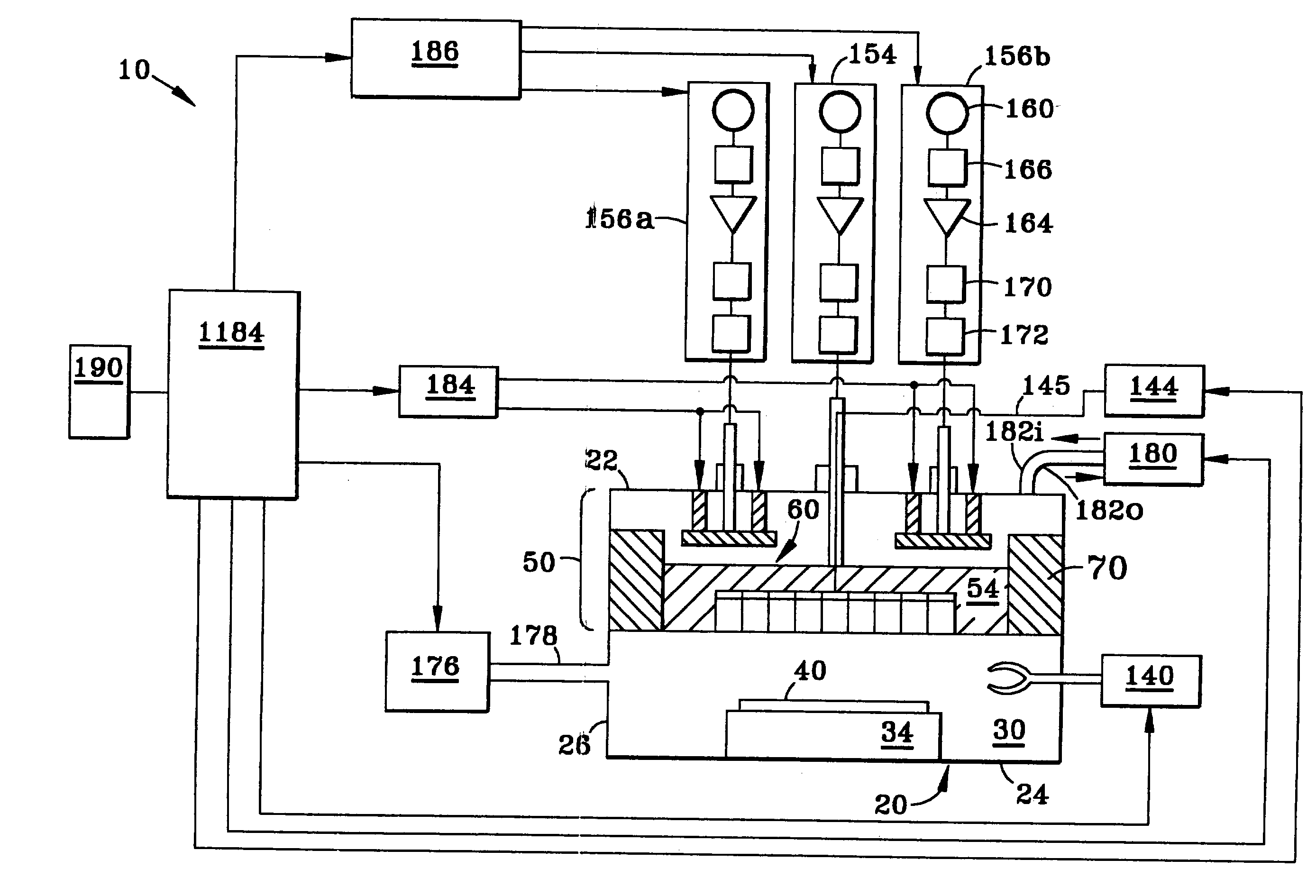
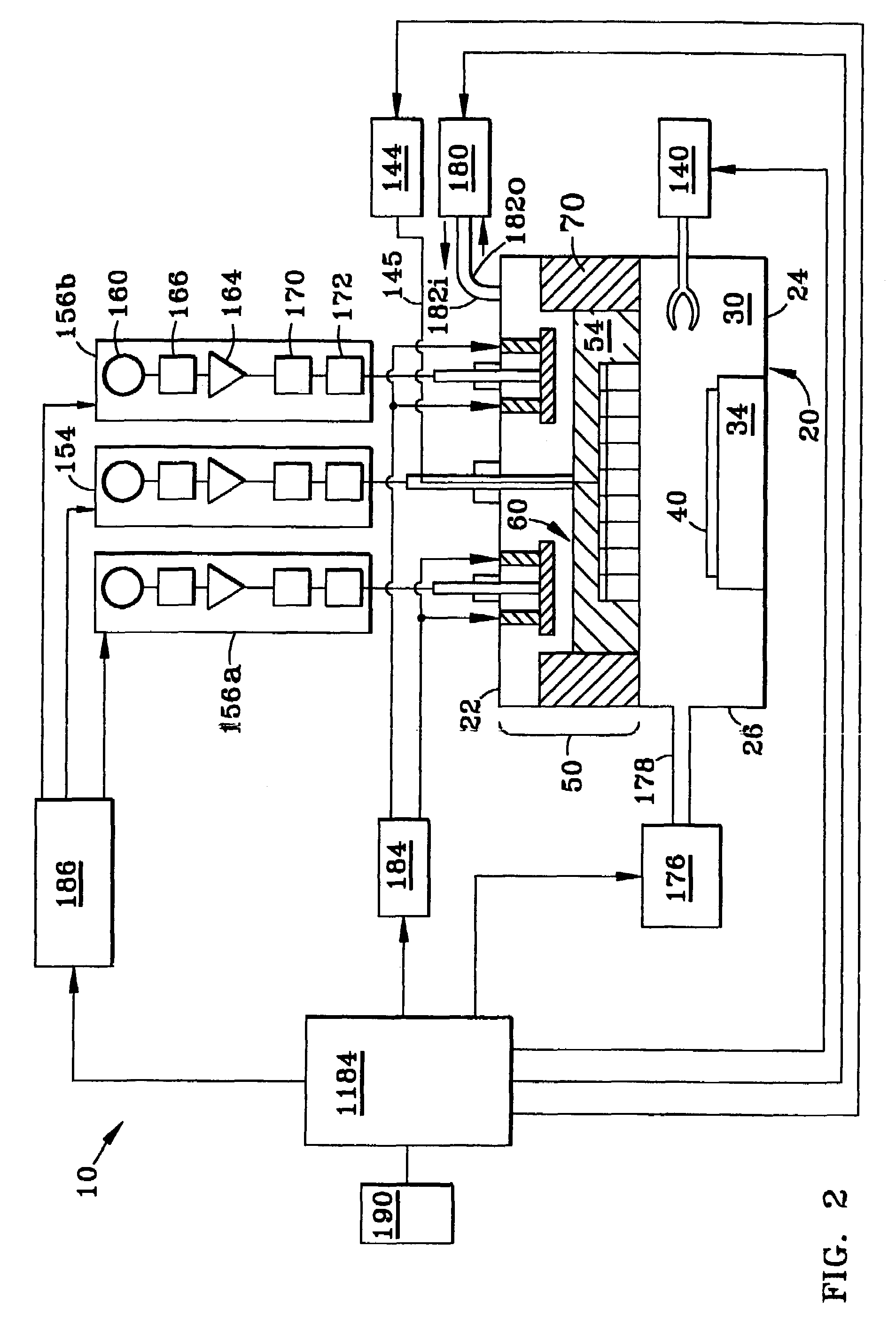
[0032]With reference now to FIGS. 2–4, plasma reactor system 10 of the present invention comprises a plasma chamber 20 with an upper wall 22, a lower wall 24, side walls 26 and an interior region 30 capable of containing a plasma. System 10 further includes within interior 30 of chamber 20 adjacent lower wall 24 a substrate support member 34 with a support surface 34S for supporting a substrate 4...


PUM

PropertyMeasurementUnit
thickaaaaaaaaaa
impedanceaaaaaaaaaa
impedanceaaaaaaaaaa

Abstract

An electrode assembly (50) and an associated plasma reactor system (10) and related methods for a variety of plasma processing applications. The electrode assembly provides control of a plasma density profile (202) within an interior region (30) of a plasma reactor chamber (20). The electrode assembly includes an upper electrode (54) having a lower surface (54L), an upper surface (54U) and an outer edge (54E). The lower surface of the upper electrode faces interior region of the plasma chamber housing the plasma (200), and thus interfaces with the plasma. The electrode assembly further includes a segmented electrode (60) arranged proximate to and preferably substantially parallel with the upper surface of the upper electrode. The segmented electrode comprises two or more separated electrode segments (62a, 62b, . . . 62n), each having an upper and lower surface. Each electrode segment is spaced apart from the upper electrode upper surface by a corresponding controlled gap (Ga, Gb, . . . Gn). The electrode assembly may further include one or more actuators (110) attached to one or more electrode segments at the upper surface of the one or more electrode segments. The actuators allow for movement of the one or more electrode segments to adjust one or more of the controlled gaps. The adjustable controlled gaps allow for controlling the shape of the plasma density profile within the interior region of the chamber, thereby allowing for a desired plasma process result.

Description

[0001]This is a Divisional application of U.S. Continuation application No. 10 / 189,425, filed on Jul. 8, 2002 now U.S. Pat. No. 6,863,020, as a Continuation of International Application PTC / US01 / 00120, filed on Jan. 3, 2001, and claims benefit of U.S. Application No. 60 / 175,284, filed Jan. 10, 2000, the contents of which are incorporated herein in their entirety by reference.[0002]The present invention relates to plasma processing, and more particularly pertains to electrodes associated with plasma processing apparatus and methods for controlling the plasma.BACKGROUND OF THE INVENTION[0003]In semiconductor manufacturing, plasma reactor chambers are used to remove or deposit material on a semiconductor substrate in the process of making integrated circuit (IC) devices. A key factor in obtaining the highest yield and overall quality of ICs is the uniformity of the etching and deposition processes.[0004]A problem that has plagued prior art plasma reactors is the control of the plasma t...

Claims


Application Information

Patent Timeline
Patent Type & Authority Patents(United States)
IPC IPC(8): H01J37/32C23C16/44H01L21/205H01L21/3065
CPCH01J37/32082H01J37/32532H01J37/32568
Inventor MITROVIC, ANDREJ S.
Owner TOKYO ELECTRON LTD
Why Eureka
Try Eureka