High resolution imaging lidar for detecting submerged objects

Inactive Publication Date: 2005-11-08
THE UNITED STATES OF AMERICA AS REPRESENTED BY THE SECRETARY OF THE NAVY
View PDF26 Cites 64 Cited by
  • Summary
  • Abstract
  • Description
  • Claims
  • Application Information

AI Technical Summary

Benefits of technology

[0008]An advantage of the imaging lidar of the present invention is that the scanning beam may be pulsed at a rate sufficient for high data acquisition rates used in high resolution imaging applications and at a high energy efficiency suitable for airborne platforms.
[0009]Another advantage is that the signal-to-noise ratio may be substantially im

Problems solved by technology

A slower scan rate would increase the data acquisition time, causing vulnerability in hostile environments, or reduce the image resolution.
A problem with current scanning lidars is that they perform poorly in ambient light.
Because blue-green lasers are typically used for underwater transmission, sunlight scattered back to the photomultiplier tube degrades the signal to noise ratio.
Another problem is that surface sc

Method used


Image

  • High resolution imaging lidar for detecting submerged objects
  • High resolution imaging lidar for detecting submerged objects

Examples


Example

[0013]The following description is presented solely for the purpose of disclosing how the present invention may be made and used. The scope of the invention is defined by the claims.

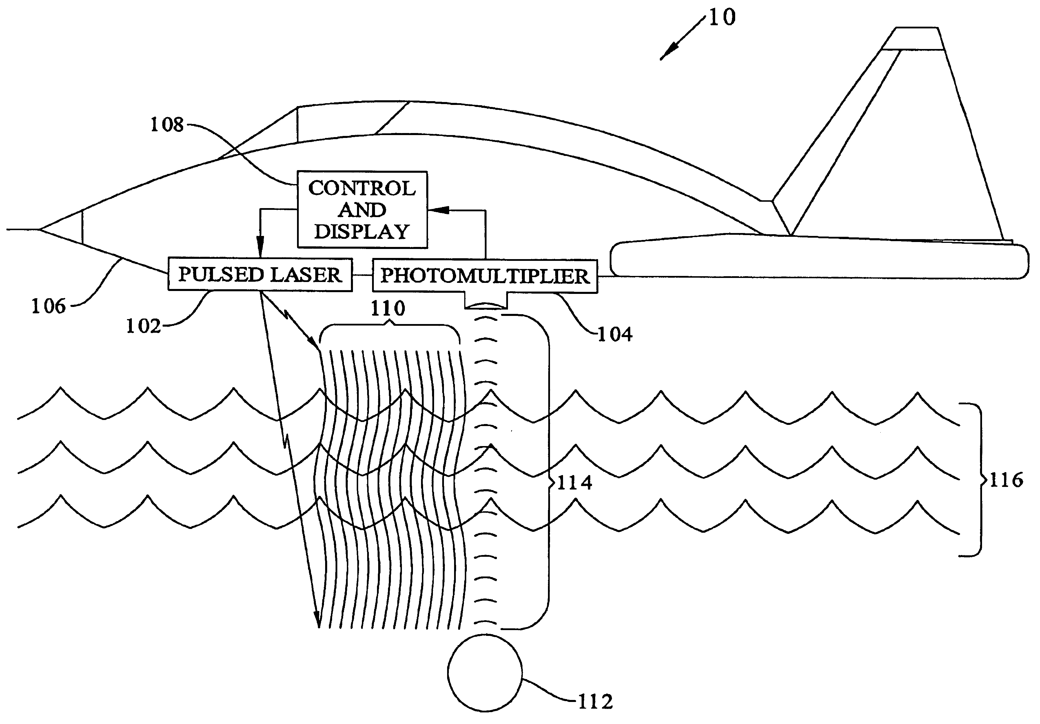
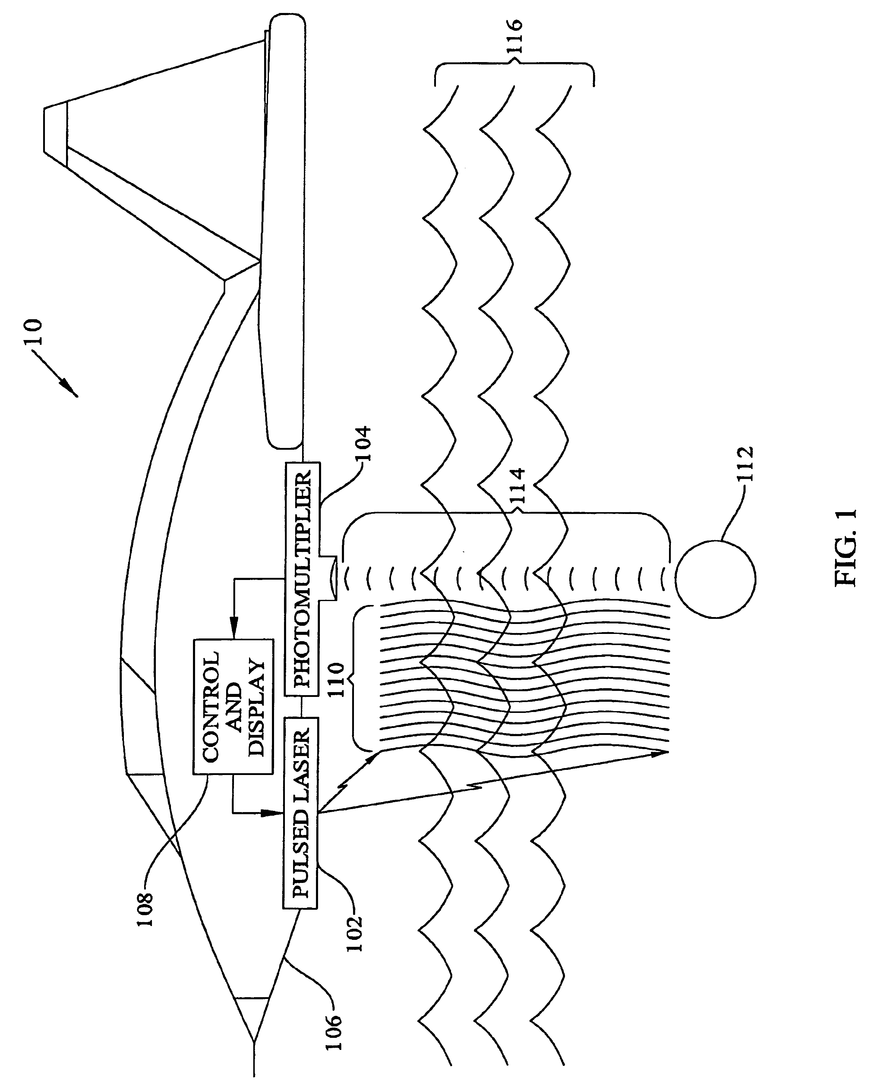
[0014]In FIG. 1 an imaging lidar system 10 of the present invention comprises a pulsed laser 102, a photomultiplier 104, and a control / display 108. An aircraft 106, by way of example, may be used to provide relative motion of the lidar components over water surface 116. Pulsed laser 102 may be made as in U.S. Pat. No. 5,530,711 issued to Richard Scheps on Jun. 25, 1996 incorporated herein by reference thereto and configured with photomultiplier 104 and control / display 108 as described in U.S. Pat. No. 4,143,400 issued to Paul Heckman et al. on Mar. 6, 1979 incorporated herein by reference thereto.

[0015]In operation pulsed laser 102 emits pulses in, for example, the blue-green wavelength region for optimum transmission in water at a rate of, for example, 700 KHz to match the data acquisition rate of typic...


PUM


Abstract

An image lidar includes a laser for generating light beam pulses in a line scan to illuminate an area surrounding a target. A controller selects pulse width and pulse rate of the light beam pulses emitted by the laser. A photomultiplier tube detects energy from the light beam pulses scattered by the target and generates a series of pixels defined by the light beam pulses and the line scan. A display generates an image from the pixels that is representative of the target.

Description

BACKGROUND OF THE INVENTION[0001]The present invention relates to the detection of submerged objects in a scattering medium such as water. More specifically, but without limitation thereto, the present invention relates to a device for forming high resolution images of objects submerged in shallow water and coastal regions from an airborne platform using improved lidar (light detection and ranging, analogous to radar, i.e., radio detection and ranging) to provide high resolution imaging.[0002]A number of military and civilian applications require searching for certain objects in a scattering medium. For example, moored and bottom mines deployed in shipping lanes generally must be detected before measures can be taken to disarm them. It is also useful in various applications to locate and map submerged obstacles, cables, pipelines, barrels, oil drums, etc.[0003]An imaging lidar is commonly applied to the problem of detecting submerged objects in shallow water, such as mines. An exemp...

Claims


Application Information

Patent Timeline
IPC IPC(8): H04N7/00G01S17/18G01S17/88G01S17/89
CPCG01S17/107G01S17/88G01S17/89G01S17/18
Inventor SCHEPS, RICHARD
Owner THE UNITED STATES OF AMERICA AS REPRESENTED BY THE SECRETARY OF THE NAVY
Why Eureka
Try Eureka