
Method and apparatus for inspecting an EUV mask blank

a mask blank and mask technology, applied in the field of extreme ultraviolet lithography, can solve the problems of not well characterizing the sample, missing significant features of the mask blank, and a small sampling area of the measurement position on the mask blank, and achieve the effect of large area and fast inspection

Inactive Publication Date: 2005-11-08
EUV
View PDF20 Cites 10 Cited by
  • Summary
  • Abstract
  • Description
  • Claims
  • Application Information

AI Technical Summary

Benefits of technology

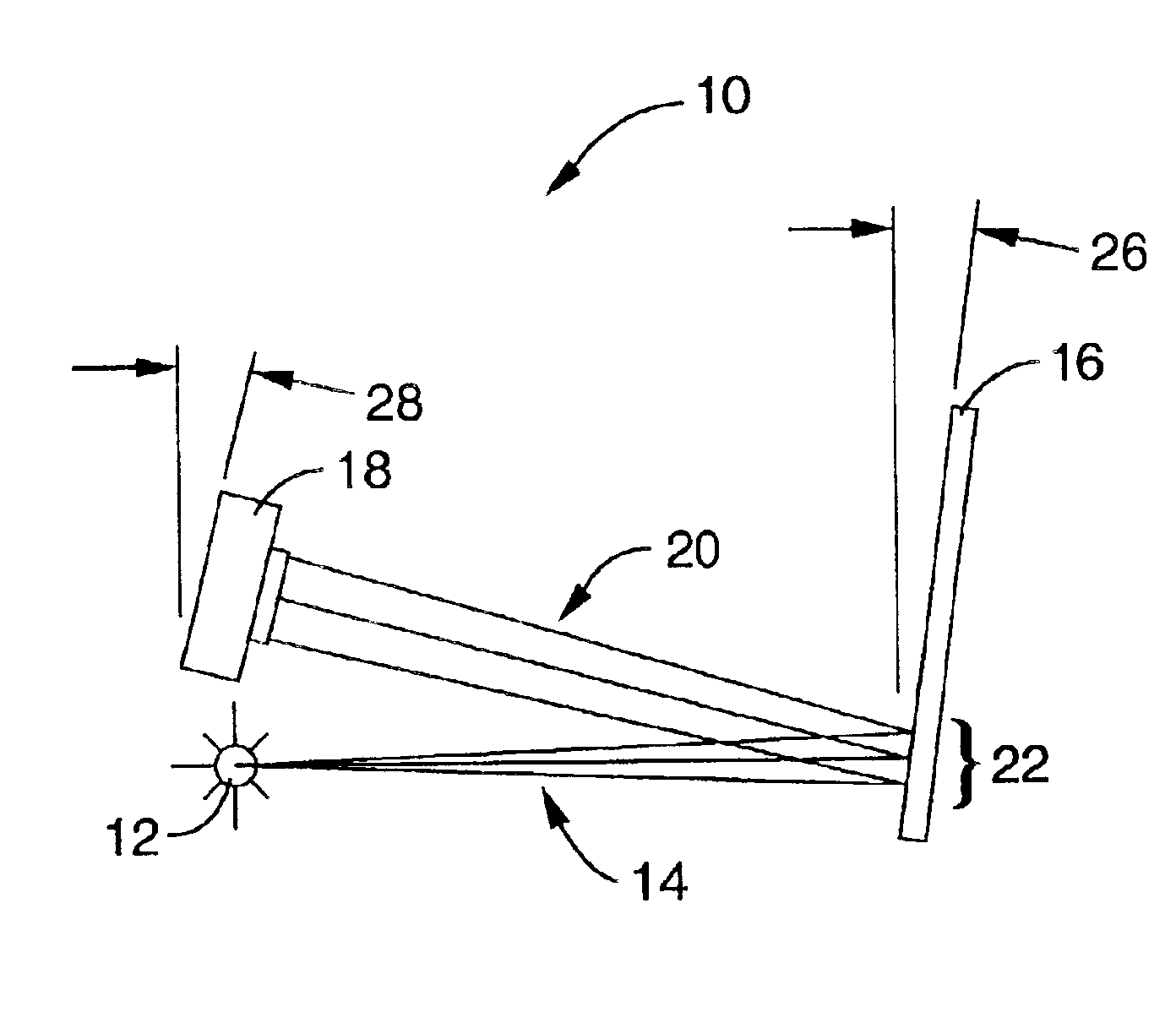
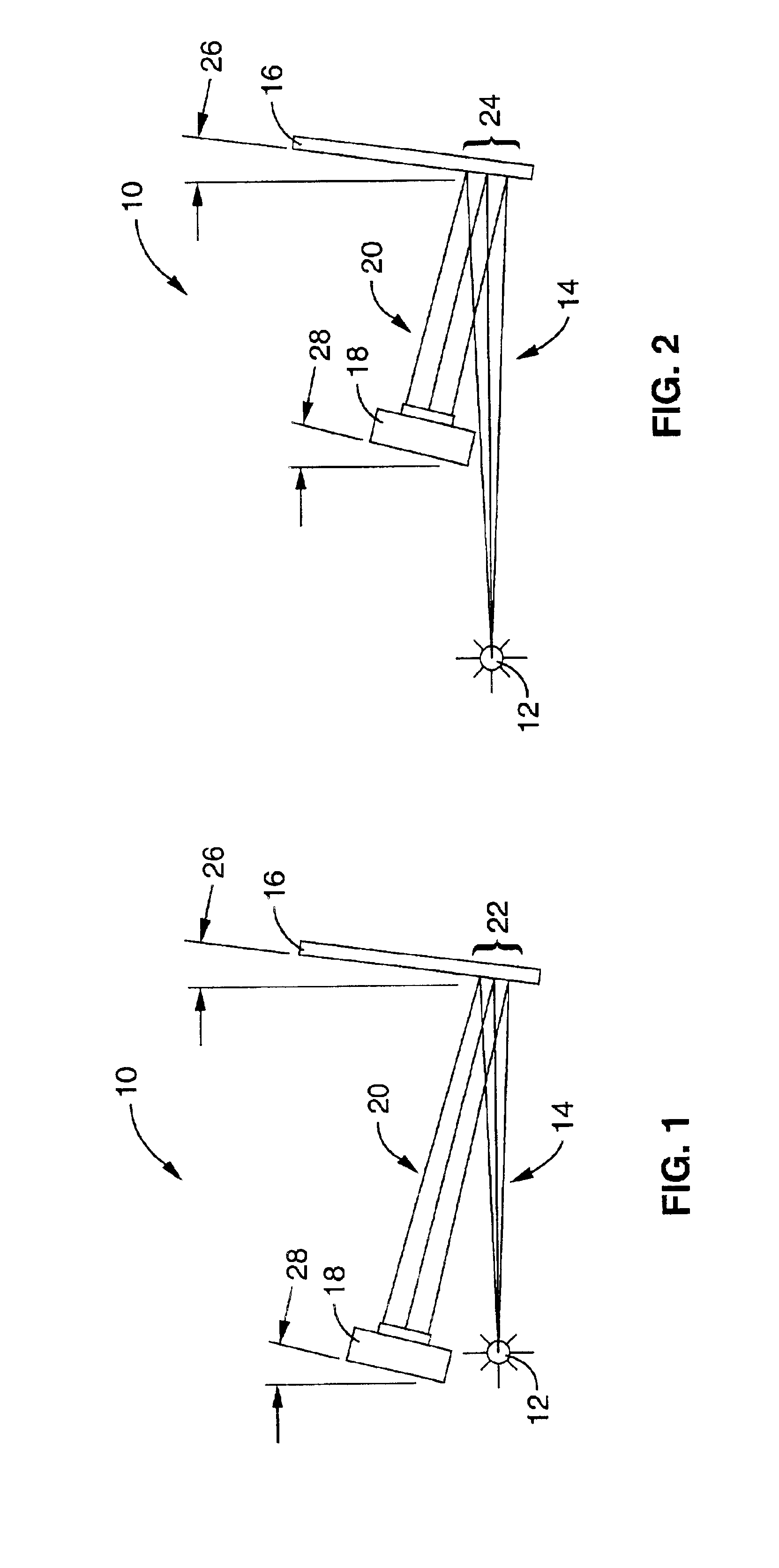
[0011]The present invention pertains to a fast, large area, course preliminary inspection system for mask blank used in EUV lithography. By way of example, and not of limitation, the system comprises an EUV light source such as a synchrotron that directs a beam of light to a reflective mask blank, and an EUV detector such as a mega-pixel CCD camera array or micro-channel plate positioned to record the reflection from a relatively large area (i.e., multiple spots) of the mask blank in a single exposure. The system provides a 1:1 mapping of a large area of the mask blank, where each pixel in the array corresponds to a small area on the mask blank. This ability of the system to simultaneously record multiple spots of the mask blank provides for a faster inspection than conventional point by point inspection of small areas on the mask blank.
[0017]Another object of the invention is to accurately and efficiently inspect large numbers of EUV mask blanks.

Problems solved by technology

Where the spot is small, concern may arise that a sparse sampling of measurement positions on the mask may miss significant features.
On the other hand, where the spot is relatively large, it may average together high- and low-quality regions producing results that may not characterize the sample well.

Method used


Image

  • Method and apparatus for inspecting an EUV mask blank
  • Method and apparatus for inspecting an EUV mask blank
  • Method and apparatus for inspecting an EUV mask blank

Examples


Embodiment Construction

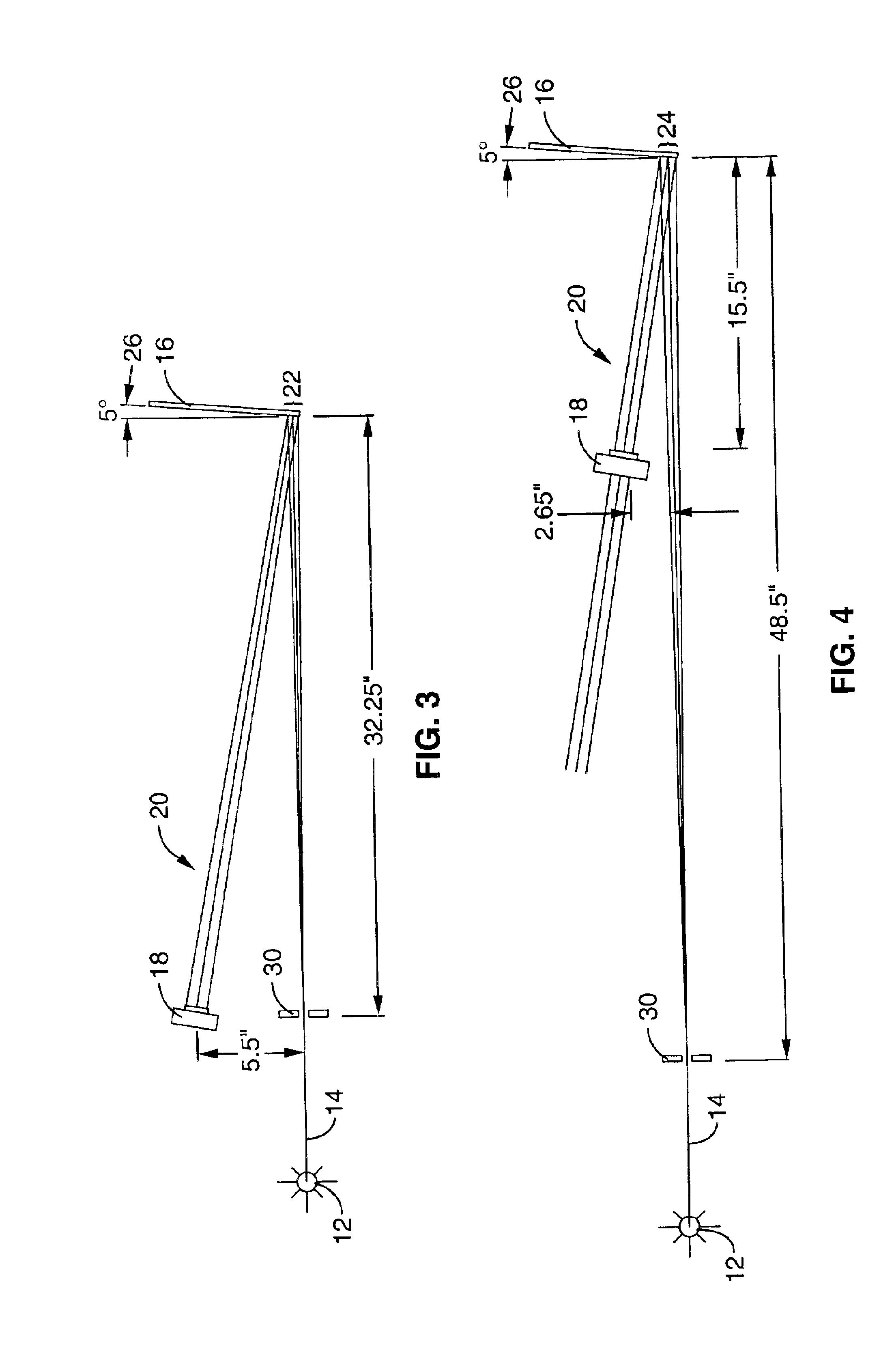
[0027]The invention will now be described with reference to FIG. 1 through FIG. 6, where like reference numbers denote like parts. It will be appreciated that the apparatus may vary as to configuration and as to details of the parts, and that the method may vary as to the specific steps and sequence, without departing from the basic concepts as disclosed herein.

[0028]Referring first to FIG. 1 and FIG. 2, an apparatus 10 for inspecting mask blanks for defects according to the present invention is shown. As used herein, the term “defect” is intended to encompass any kind of non-uniformity that may arise in the reflectivity of multi-layer mirrors. As can be seen, the apparatus comprises an EUV light source 12, such as a synchrotron or the like, that directs a beam of light 14 to a mask blank 16, and an EUV detector 18 such as a CCD camera array or micro-channel plate positioned to record the reflection 20 from a relatively large area of mask blank 16 in a single exposure. Mask blank 16...


PUM

PropertyMeasurementUnit
reflectivityaaaaaaaaaa
angle of incidenceaaaaaaaaaa

Abstract

An apparatus and method for at-wavelength EUV mask-blank characterization for inspection of moderate and low spatial frequency coating uniformity using a synchrotron or other source of EUV light. The apparatus provides for rapid, non-destruction, non-contact, at-wavelength qualification of large mask areas, and can be self-calibrating or be calibrated to well-characterized reference samples. It can further check for spatial variation of mask reflectivity or for global differences among masks. The apparatus and method is particularly suited for inspection of coating uniformity and quality and can detect defects in the order of 50 μm and above.

Description

STATEMENT REGARDING FEDERALLY SPONSORED RESEARCH OR DEVELOPMENT[0001]This invention was made with Government support under contract No. DE-AC03-76SF00098, awarded by the Department of Energy. The Government has certain rights in this invention.CROSS-REFERENCE TO RELATED APPLICATIONS[0002]Not ApplicableREFERENCE TO A MICROFICHE APPENDIX[0003]Not ApplicableBACKGROUND OF THE INVENTION[0004]1. Field of the Invention[0005]The present invention pertains generally to extreme ultraviolet lithography (EUVL), and more particularly to at-wavelength inspection of reflective multilayer-coated mask blanks.[0006]2. Description of the Background Art[0007]Reflective extreme ultraviolet light (EUV) mask blanks, which are fabricated and subsequently patterned, are becoming critical elements in a relatively new photolithographic technology that incorporates EUV light. Mask blanks are formed from large (e.g., typically greater than four-inch square or diameter) substrates coated with a spatially uniform...

Claims


Application Information

Patent Timeline
Patent Type & Authority Patents(United States)
IPC IPC(8): G03F1/00G03F1/84
CPCG03F1/84
Inventor GOLDBERG, KENNETH A.
Owner EUV
Learn More