
Hydraulic pressure generating apparatus

a technology of hydraulic pressure and generating apparatus, which is applied in the direction of fluid couplings, positive displacement liquid engines, servomotors, etc., can solve the problems of large scale and complexity of machine construction, and the installation of oil feeding pumps outside the oil tank becomes unnecessary, so as to improve safety and facilitate maintenance

Active Publication Date: 2005-11-15
KK TOSHIBA
View PDF4 Cites 4 Cited by
  • Summary
  • Abstract
  • Description
  • Claims
  • Application Information

AI Technical Summary

Benefits of technology

[0013]The present invention is achieved in light of the fact described above and an object thereof is to substantially eliminate defects or drawbacks encountered in the prior art mentioned above and to provide a hydraulic pressure generating apparatus capable of being sufficiently intended for miniaturization of the construction of the apparatus, cost reduction, facility of maintenance, and improvement in safety in consideration of various installation conditions, operation conditions, inspection conditions, etc. in relation to the steam turbine, gas turbine, and the like.
[0014]In the case where phosphoric acid ester oil, which is easily deteriorated by direct heating, is applied for hydraulic pressure control of a generator or motor of such as steam turbine, there were provided problems, as mentioned above, of large scale and complexity of the machine construction because the oil tank is heated from surroundings as indirect heating type and a tank surrounding wall and a device for feeding warm air are provided. The inventors studied and analyzed various characters regarding flame resistant hydraulic oil, and as a result, they confirmed the existence of an oil that is only slightly deteriorated by direct heating among recently developed flame resistant hydraulic oils. That is, they found that, by applying such flame resistant hydraulic oil, the direct heating can be performed, and, by providing a direct heating type heater within the oil tank, the tank surrounding wall and the device for feeding warm air can be omitted for miniaturization and simplification of the machine construction, as well as extreme reduction of costs and labor in operation, maintenance, etc.
[0015]Further, in the case where the oil tank having such construction is applied, installation of an oil feeding pump within the oil tank becomes easier, and installation of the oil feeding pump outside of the oil tank becomes unnecessary. By omitting the external pipes or like, simplification of the construction and the improvement in maintenance can be intended. Further, it is to be noted that, in the hydraulic oil, since water within the air mixed into the oil during operation is condensed, the oil mixed with the water is possibly fed to the hydraulic pressure system if the oil feeding pump is simply installed within the oil tank. It is not preferable that, when water is mixed, the flame resistant hydraulic oil is clouded and air bubble is generated, and the hydraulic oil cannot exert performance originally as hydraulic oil. To this regard, the inventors found that, by applying the flame resistant hydraulic oil having a specific gravity less than 1, and holding the separated state by sinking the water at the inside bottom of the oil tank using difference of specific gravity from water, while by preventing the water from mixing into the hydraulic oil by disposing the oil feeding pump on the side upper than the bottom portion within the oil tank, the occurrence of the above described phenomena can be prevented and the hydraulic oil in a good state can be suctioned from the oil feed pump.
[0016]Further, regarding the points that, since phosphoric acid ester oil is easily oxidized, the hydraulic pressure generating apparatus using the phosphoric acid ester requires activated clay filter to cause complexity of the system, and since the phosphoric acid ester oil has toxicity, the maintenance is interrupted by the necessity of avoiding contact with a human body, the inventors found that these points can be accommodated by using flame resistant oil having high oxidation resistance and low toxicity as the control oil.
[0023]In a still further aspect, in such apparatus, the control oil is flame resistant hydraulic oil having low toxicity.
[0043]According to the present invention of the characters and structures mentioned above, there is provided the hydraulic pressure generating apparatus capable of achieving the miniaturization of the construction of the apparatus, cost reduction, facility of maintenance, and improvement in safety in consideration of various installation conditions, operation conditions, inspection conditions, and the like in relation to the steam turbine, gas turbine, and the like generator.

Problems solved by technology

In the case where phosphoric acid ester oil, which is easily deteriorated by direct heating, is applied for hydraulic pressure control of a generator or motor of such as steam turbine, there were provided problems, as mentioned above, of large scale and complexity of the machine construction because the oil tank is heated from surroundings as indirect heating type and a tank surrounding wall and a device for feeding warm air are provided.
Further, in the case where the oil tank having such construction is applied, installation of an oil feeding pump within the oil tank becomes easier, and installation of the oil feeding pump outside of the oil tank becomes unnecessary.
Further, regarding the points that, since phosphoric acid ester oil is easily oxidized, the hydraulic pressure generating apparatus using the phosphoric acid ester requires activated clay filter to cause complexity of the system, and since the phosphoric acid ester oil has toxicity, the maintenance is interrupted by the necessity of avoiding contact with a human body, the inventors found that these points can be accommodated by using flame resistant oil having high oxidation resistance and low toxicity as the control oil.

Method used


Image

  • Hydraulic pressure generating apparatus
  • Hydraulic pressure generating apparatus
  • Hydraulic pressure generating apparatus

Examples


Embodiment Construction

[0048]Hereinafter, embodiments of a hydraulic pressure generating apparatus according to the invention will be described with reference to the accompanying drawings.

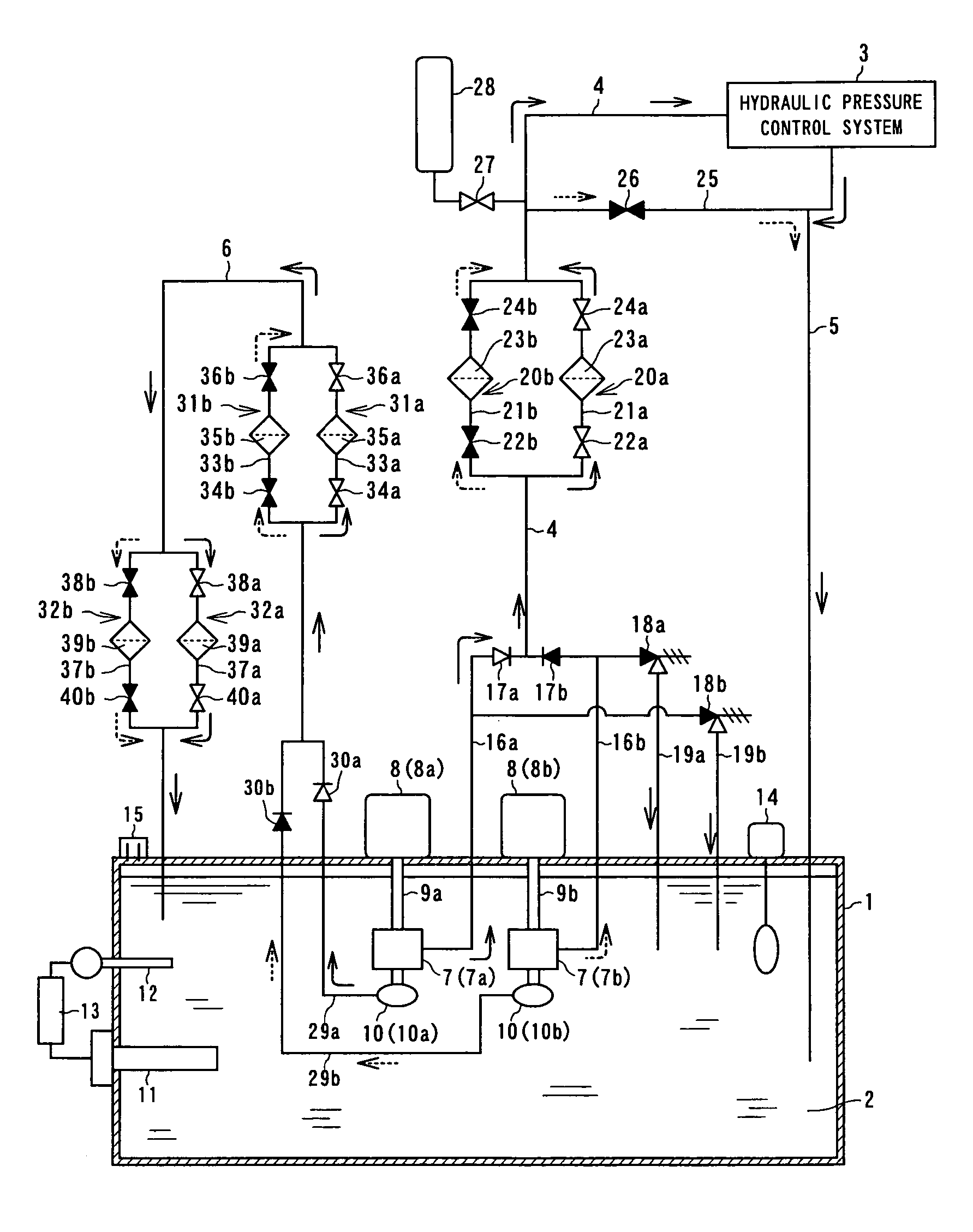
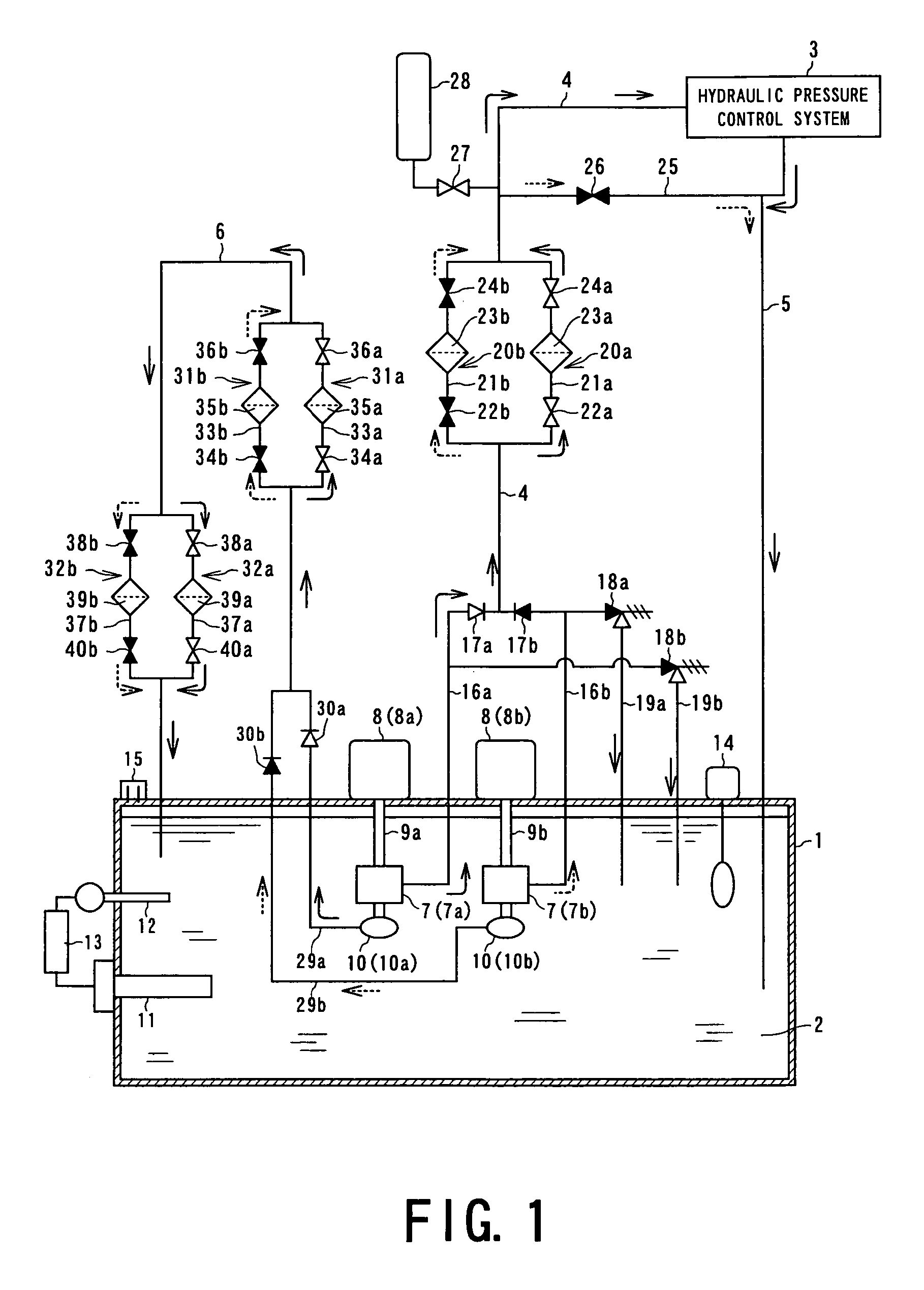
[0049]FIG. 1 is a schematic diagram showing the hydraulic pressure generating apparatus according to one embodiment of the invention, which is applied to an hydraulic pressure control system of such as a steam turbine or gas turbine.

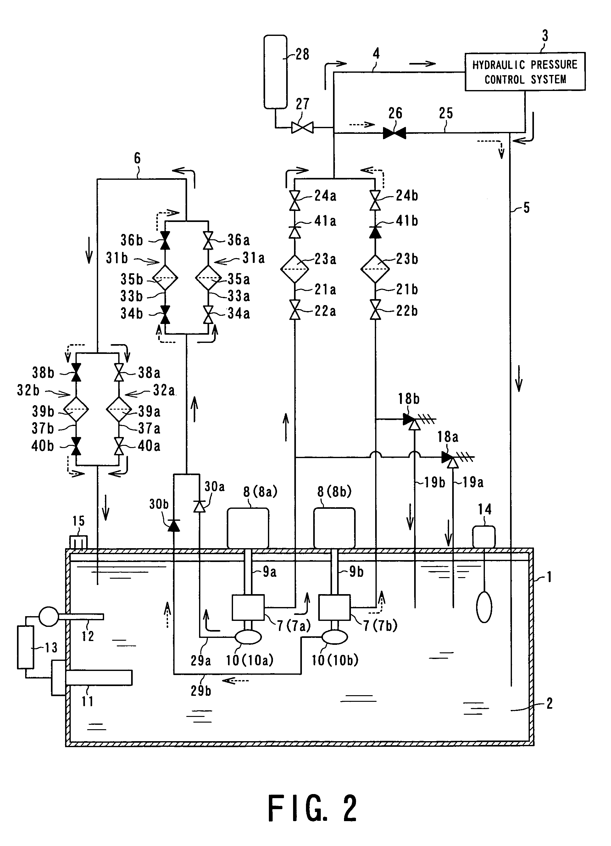
[0050]As shown in FIG. 1, the hydraulic pressure generating apparatus includes an oil tank 1, a hydraulic oil feed line 4 for feeding hydraulic oil 2 accommodated in the oil tank 1 to an hydraulic pressure control system 3 such as a steam turbine or gas turbine with high pressure, a hydraulic oil return line 5 for returning drain oil from the hydraulic pressure control system 3 to the oil tank 1, and a circulation line 6 for performing purification or cooling by circulating the hydraulic oil 2 of the oil tank 1.

[0051]The oil tank is constituted by a sealed box type container, for example, and...


PUM


Abstract

A hydraulic pressure generating apparatus includes a hydraulic oil feed line for feeding hydraulic oil with high pressure from an oil tank to a hydraulic pressure control system of a generator by an oil feeding pump unit, a hydraulic oil return line for returning drain oil from the hydraulic pressure control system to the oil tank, and a circulation line for circulating and purifying the hydraulic oil of the oil tank by a circulating pump unit. In such apparatus, the hydraulic oil is flame resistant hydraulic oil which is hardly deteriorated by direct heating, and the flame resistant hydraulic oil is heated by a heater disposed in the oil tank.

Description

BACKGROUND OF THE INVENTION[0001]1. Field of the Invention[0002]The present invention relates to a hydraulic pressure generating apparatus for feeding high pressure flame resistant (resisting) hydraulic oil to a hydraulic pressure control system of a generator (or motor) of such as a steam turbine and gas turbine, specifically, to a hydraulic pressure generating apparatus intended for making the apparatus construction compact, reducing costs, improving facility of maintenance and safety in operation.[0003]2. Relevant Art[0004]Conventionally, in a hydraulic pressure control system applied to a generator of such as a steam turbine and gas turbine, flame resistant hydraulic oil, specifically, phosphoric acid ester oil is applied with high pressure and high cleanliness for quickly activating control valves, feeding clean control oil to servo valves, and preventing fire from generating due to leakage of the control oil.[0005]However, since phosphoric acid ester oil has viscosity which va...

Claims


Application Information

Patent Timeline
IPC IPC(8): F15B1/26F15B1/00F15B21/00F15B21/04F15B21/06F04B23/02F15B21/041F04B23/04F04B53/10F15B21/0423F15B21/0427
CPCF15B1/26F15B21/041F15B21/042F15B21/06F15B21/0423F15B21/0427Y10T137/86163Y10T137/86059
Inventor TAKAHASHI, MAKOTOSHINDO, OSAMUNARABE, ATSUSHI
Owner KK TOSHIBA
Learn More