
Hydrodynamic pressure bearing system and spindle motor using the same

a technology of hydraulic pressure bearings and spindles, which is applied in the direction of sliding contact bearings, instruments, and record information storage, etc., can solve the problems of fluid sealing in the clearance, reducing the rotation accuracy, and changing the dimension, so as to reduce the variations of the clearance and increase the finishing accuracy of the clearance forming portion.

Inactive Publication Date: 2005-11-15
MINEBEA CO LTD
View PDF1 Cites 15 Cited by
  • Summary
  • Abstract
  • Description
  • Claims
  • Application Information

AI Technical Summary

Benefits of technology

The present invention provides a hydrodynamic pressure bearing system and a spindle motor that can reduce variations in clearance between a rotating member and a supporting member due to thermal expansion, and increase the finishing accuracy of clearance forming portions. This is achieved by using crystallized glass for at least one of the supporting member and the rotating member, which has low thermal expansion and insulation properties. The heated side of the supporting member and the rotating member can also be made of crystallized glass to further reduce thermal transfer to other members. The invention improves the bearing system's performance and the surface quality of the spindle motor.

Problems solved by technology

However, the conventional hydrodynamic pressure bearing systems have the following problems: In general, the shafts and the sleeves of hydrodynamic pressure bearing systems of spindle motor for hard disk drives are made of stainless steel, having a high thermal coefficient of expansion, thus causing change in dimension with temperature to vary the clearance therebetween.
The variations in the clearance between the shaft and the sleeve exerts a direct influence on the dynamic pressure of the fluid, causing a decrease in rotation accuracy and also the leakage of the fluid sealed in the clearance.
In this case, since the shaft or sleeve on the coil side of the spindle motor easily increases in temperature, causing a temperature gradient between the shaft and the sleeve and increasing dimensional differentials due to thermal expansion, thus posing a serious problem.
Since the clearance at the rotating portion of the hydrodynamic pressure bearing system is extremely small, the existence of fine foreign matter generates friction to cause defects such as abnormal rotation and locking.
Also, when there is roughness on the surfaces of portions forming the clearance, foreign matter such as fine burrs formed during processing may drop into the clearance during the use of the bearing system.
Therefore, it is necessary to polish the surfaces of the portions forming the clearance to a mirror-smooth state after cutting, incurring high cost.

Method used


Image

  • Hydrodynamic pressure bearing system and spindle motor using the same
  • Hydrodynamic pressure bearing system and spindle motor using the same
  • Hydrodynamic pressure bearing system and spindle motor using the same

Examples


first embodiment

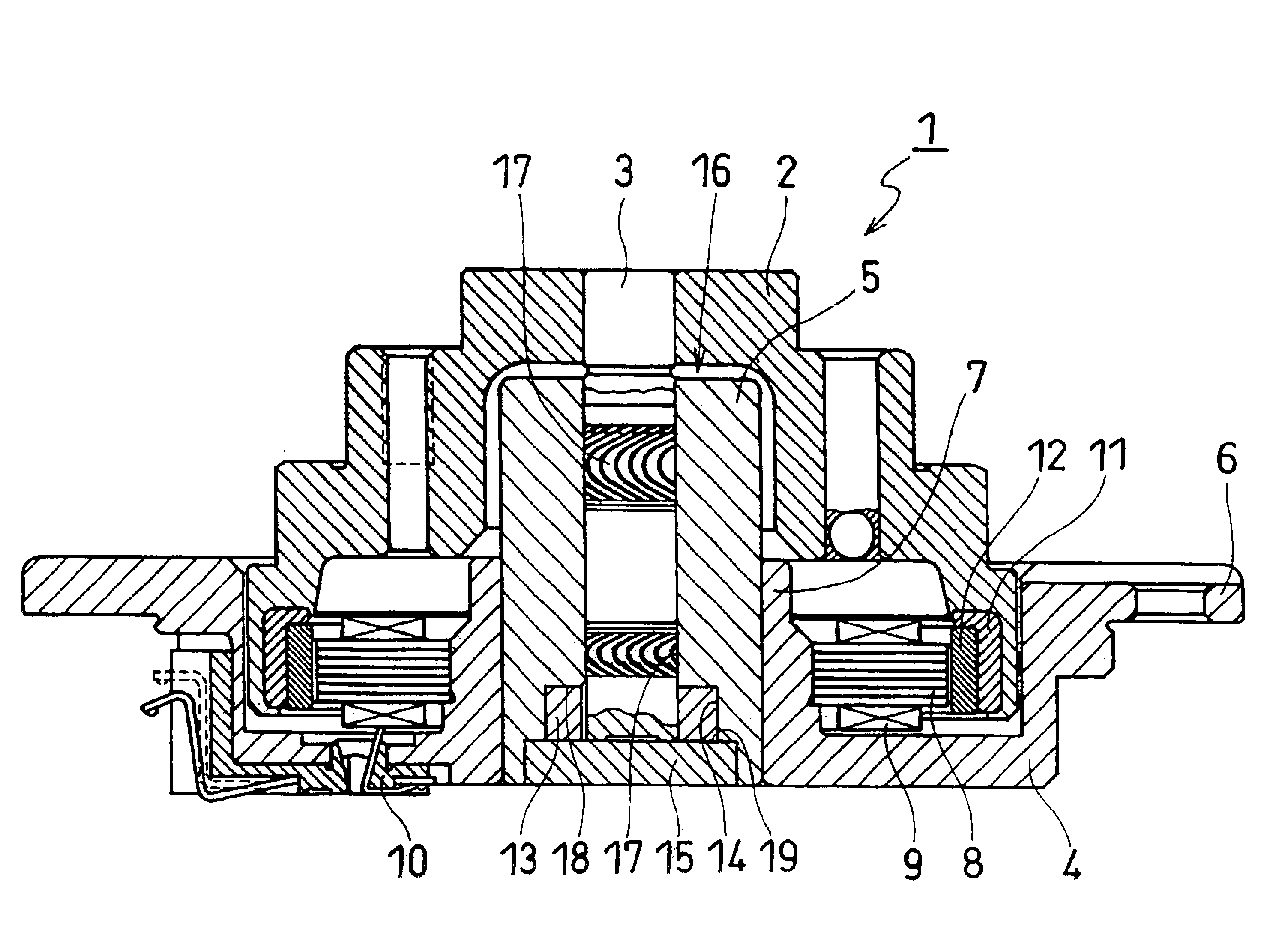
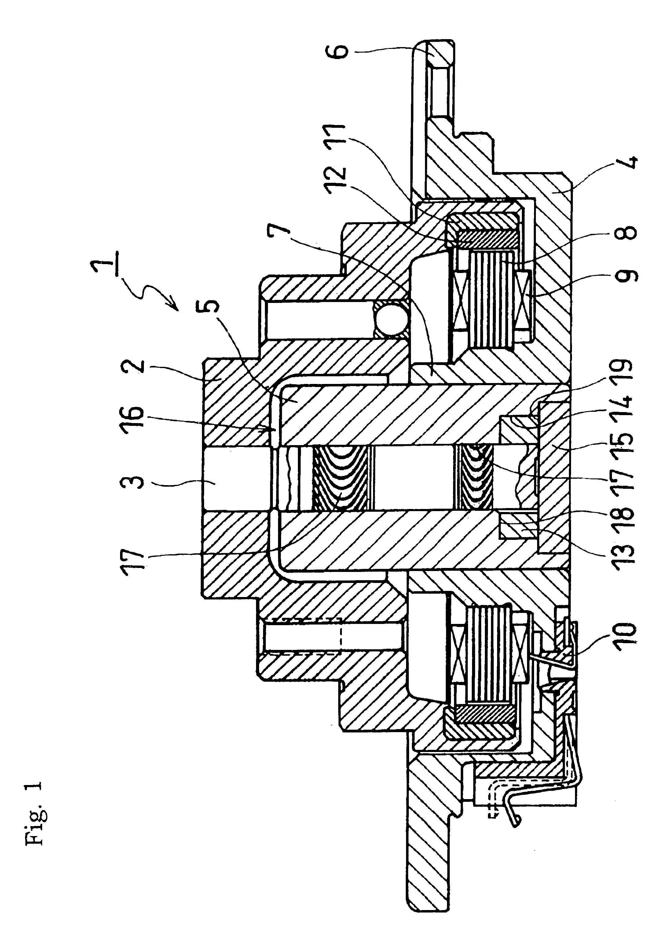
[0021]Referring to FIG. 1, the invention will be discussed. As shown in FIG. 1, a spindle motor 1 according to this embodiment uses a shaft rotating system for driving a magnetic disk in a hard disk drive of a computer or the like, wherein a shaft 3 (rotating member) secured to a hub 2 side is rotatably supported by a cylindrical sleeve 5 (supporting member) secured to a base 4 side.

[0022]The base 4 has a substantially cylindrical shape with a bottom and has a flange 6 at the rim thereof, wherein a sleeve 5 is press fitted and fixed in a cylindrical portion 7 formed at the center of the bottom. The cylindrical portion 7 has a stator stack 8 attached at the outside periphery thereof, the stator stack 8 being arranged in a ring shape and extending radially, and a coil 9 is wound around the stator stack 8. The base 4 has a connector 10 connected to the coil 9.

[0023]The hub 2 has a substantially cylindrical shape with a bottom and a stepped side, wherein the shaft 3 is press fitted in a...

second embodiment

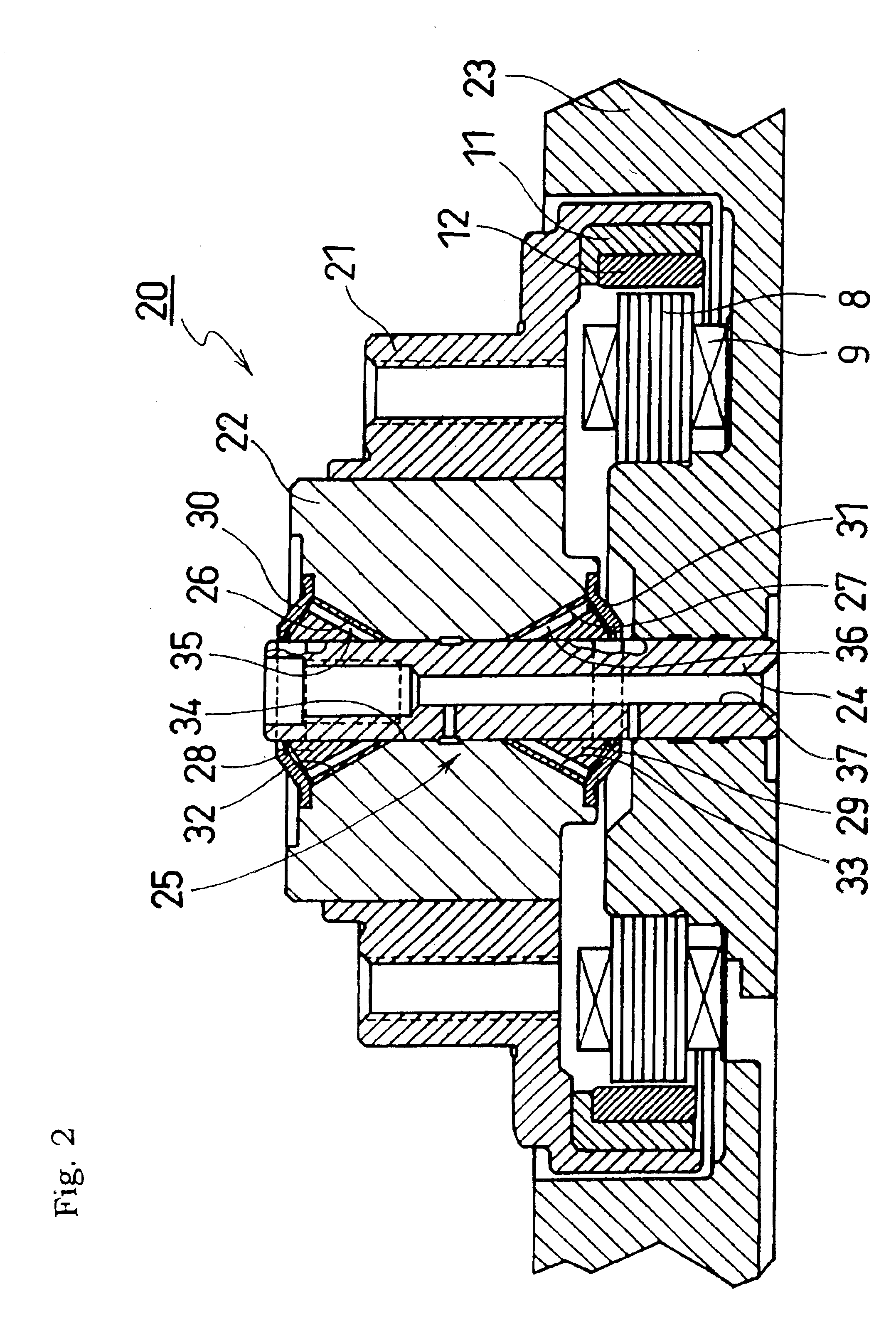
[0036]As shown in FIG. 2, a spindle motor 20 uses a fixed shaft system, wherein a sleeve 22 (rotating member) secured to a hub 21 side is rotatably supported by a shaft 24 (supporting member) secured to a base 23 side.

[0037]The base 23 has a substantially cylindrical shape with a bottom, wherein a shaft 24 is press fitted and secured by bonding in an opening formed at the center of the bottom. The stator stack 8 arranged in a ring shape and extending radially is attached to a ring-shaped recessed portion formed around a shaft mounting portion, and the coil 9 is wound around the stator stack 8. The base 23 has a connector (not shown) to be connected to the coil 9, attached thereto.

[0038]The hub 21 has a substantially cylindrical shape with a bottom and a stepped side, wherein the cylindrical sleeve 22 is press fitted and secured by bonding in an opening formed at the center of the bottom, wherein the ring-shaped yoke 11 is attached to the inner periphery of the outermost side wall o...


PUM

PropertyMeasurementUnit
temperatureaaaaaaaaaa

Abstract

A shaft secured to a hub is inserted and rotatably supported in a sleeve secured to a base. A dynamic pressure groove is formed in the inner peripheral surface of the sleeve, and lubricant is sealed between the shaft and the sleeve. The rotation of the shaft causes dynamic pressure to generate in the lubricant due to the dynamic pressure groove, supporting the shaft floatingly. The crystallized-glass sleeve allows heat generated in a coil to be hardly transferred to the shaft, thereby reducing the variations in the clearance between the shaft and the sleeve due to temperature changes to a minimum in cooperation with the crystallized-glass sleeve with a low thermal expansion coefficient. Finishing accuracy of the bearing surface can be improved by chemical polishing. Consequently, the rotation accuracy can be improved and the leakage of lubricant due to the variations in the clearance can be prevented.

Description

BACKGROUND OF THE INVENTION[0001]1. Field of the Invention[0002]The present invention relates to a hydrodynamic pressure bearing system for a spindle motor or the like for driving a magnetic disk of a hard disk drive of a computer, and a spindle motor using the same.[0003]2. Description of the Related Art[0004]Recently, in hard disk drives of computers, bearings of spindle motors for driving magnetic disks are required to have high rotation accuracy, low friction, low noise, and long life as the magnetic disks have higher density and higher rotation speed. In order to achieve such requirements, spindle motor using a hydrodynamic pressure bearing system are developed.[0005]The hydrodynamic pressure bearing system seals fluid between a shaft and a sleeve for supporting the shaft, and forms dynamic pressure grooves at the caliber of the sleeve, thereby generating dynamic pressure in the fluid by the rotation of the shaft and supporting the shaft in a floating manner by the dynamic pres...

Claims


Application Information

Patent Timeline
Patent Type & Authority Patents(United States)
IPC IPC(8): G11B17/02G11B17/022G11B17/038F16C33/24F16C17/10H02K7/08
CPCG11B17/022G11B17/038F16C17/102F16C33/043
Inventor OBARA, RIKURO
Owner MINEBEA CO LTD
Learn More