
Sintered valve metal powders for implantable capacitors

Active Publication Date: 2005-11-15
WILSON GREATBATCH LTD
View PDF14 Cites 43 Cited by
  • Summary
  • Abstract
  • Description
  • Claims
  • Application Information

AI Technical Summary

Benefits of technology

[0008]Prior to being anodized in the electrolyte, the valve metal pellet is subjected to a relatively high sintering temperature for a relatively short period of time according to the present invention. The high temperature accomplishes the goal of sintering the pressed valve metal into a coherent body while the relatively short time at peak temperature does not adversely affect the volumetric energy density of the sintered pellet.

Problems solved by technology

The problem is that when the pellet of a pressed valve metal powder is subjected to these temperatures for extended periods of up to 30 minutes, the real surface area and porosity of the anode are reduced.
It also detrimentally affects the pellet's permeability, which means that powder particles deeper in the pellet are not readily available for the production of a dielectric oxide film thereon.
This adversely increases capacitor ESR and decreases volumetric capacitance and energy density.

Method used


Image

  • Sintered valve metal powders for implantable capacitors
  • Sintered valve metal powders for implantable capacitors
  • Sintered valve metal powders for implantable capacitors

Examples


example i

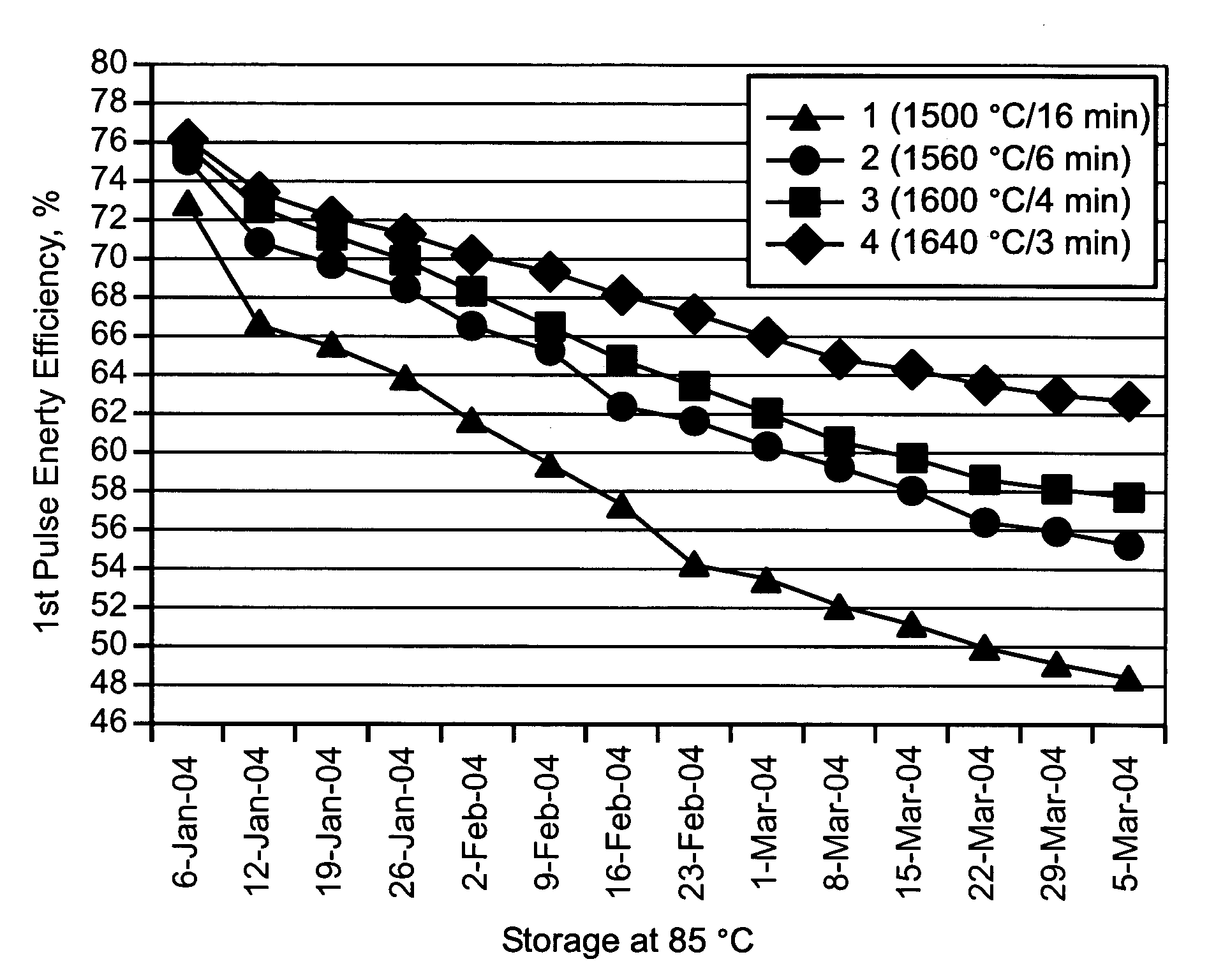
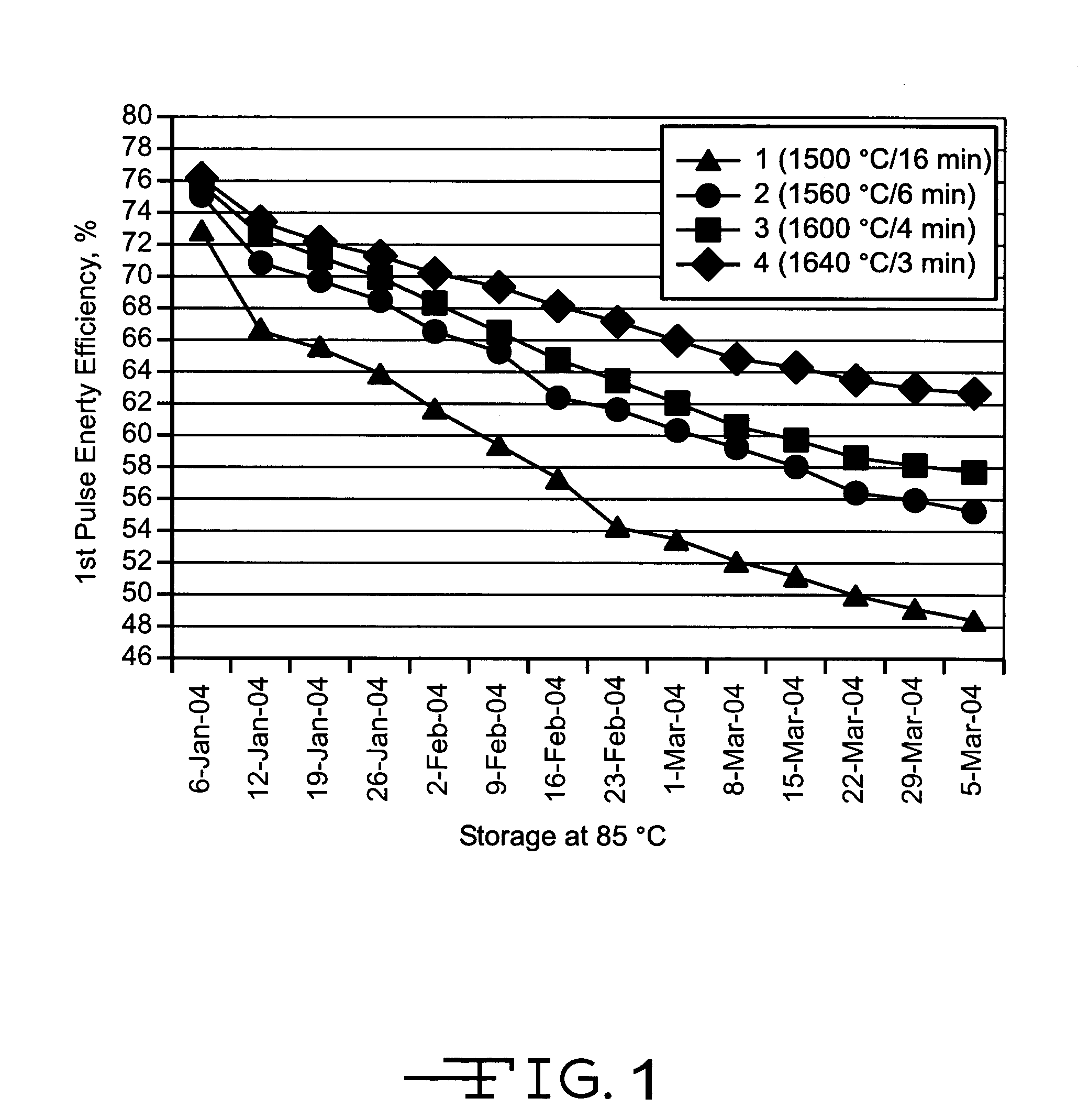
[0021]Five pressed powder tantalum pellets were sintered according to the varied conditions listed in Table 1. The pellets are designated as 1, 2, 3, 4 and 5 in the table. Pellet no. 1 was sintered at 1,500° C. for 16 minutes and served as the control. This is a relatively low temperature for a relatively long time. Pellets nos. 4 and 5 sintered at 1,640° C. for 3 and 4 minutes, respectively, had the lowest DC leakage (DCL) in units of nono-Amp / (microfarad×volt) (nA / CV), but they also had the lowest volumetric capacitance (AC capacity / cc) and energy density (J / cc). Pellet no. 3 sintered at 1,600° C. for 4 minutes exhibited lower DC leakage than the control pellet no. 1 while still maintaining a high volumetric capacitance and energy density.

[0022]

TABLE 1Run #SinteringACCap / ccnA / CVJ / cc1 1500 C. / 16 min294.21.279.3421560 C. / 6 min291.40.649.2231600 C. / 4 min294.90.549.3041640 C. / 3 min288.70.459.1551640 C. / 4 min288.10.449.02

[0023]FIG. 1 is a graph of the 1st charge / discharge pulse energy ...

example ii

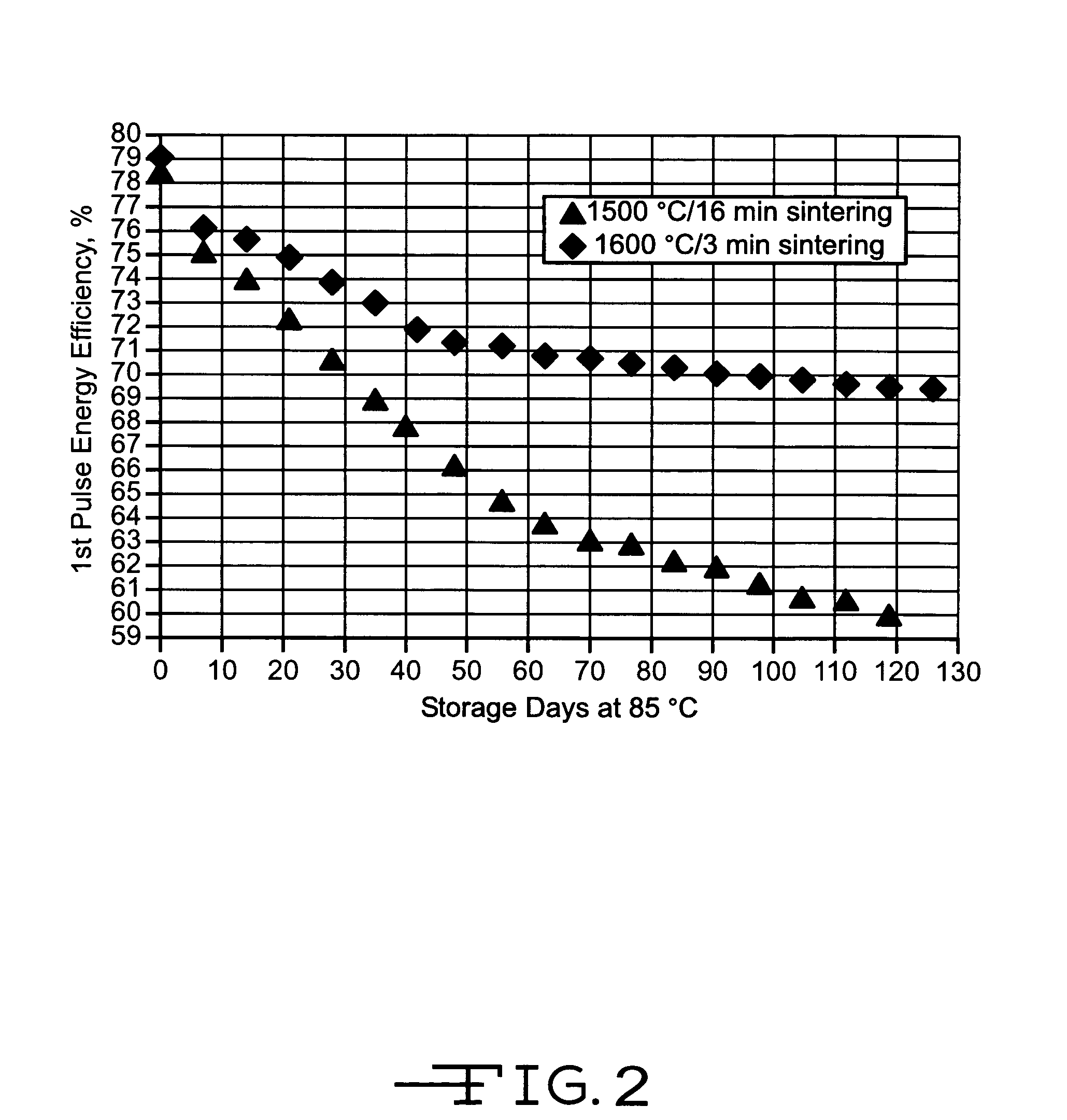
[0024]Twelve pressed powder tantalum pellets were divide into two groups. Group I contained five pellets sintered at 1,500° C. for 16 minutes and served as a control. Group II contained seven pellets sintered at 1,600° C. for 3 minutes. This is listed in Table 2.

[0025]

TABLE 2SinteringCapacitanceDCLEnergy(° C. / min.)(μF / cc)(μA)(J / cc)Group I1500 / 1640046.59.238Group II1600 / 3 39738.99.17 

[0026]FIG. 2 is a graph of the average 1st charge / discharge pulse energy efficiency (E %) at 37° C. versus storage time at 85° C. for the various pellets listed in Table 2. Again, the improvement in energy efficiency stability of the Group II pellets sintered according to the present invention is demonstrated.

[0027]Thus, an optimal sintering protocol for a given powder morphology and formation voltage is at a relatively higher temperature with a shorter sintering time than is used in conventional practice. This allows for improved long term performance stability while still maintaining a high volumetric ...


PUM

PropertyMeasurementUnit
Temperatureaaaaaaaaaa

Abstract

A sintering method for valve metal powders, such as tantalum, niobium, aluminum, titanium, and their alloys, is described. The valve metal powders are pressed into a pellet and sintered at a relatively high temperature, but for a relatively short time. The anodized valve metal structure is then useful as an anode in an electrolytic capacitor.

Description

CROSS-REFERENCE TO RELATED APPLICATION[0001]This application claims priority from provisional application Ser. No. 60 / 528,917, filed Dec. 11, 2003.BACKGROUND OF THE INVENTION[0002]1. Field of the Invention[0003]This invention generally relates to sintering of a valve metal powder for use as an anode in an electrolytic or an electrochemical / electrolytic hybrid capacitor. Suitable valve metals include, but are not limited to, tantalum, niobium, aluminum, titanium, and their alloys.[0004]2. Prior Art[0005]An electrolytic or an electrochemical / electrolytic hybrid capacitor can comprise a sintered porous anode body of valve metal such as tantalum or aluminum. Conventionally, the sintering process begins by molding a powder of the valve metal under pressure to form a molded piece or pellet having a desired shape. An anode lead wire of the valve metal is first imbedded into the powder before it is molded into the shaped pellet. The wire can also be welded to the pellet. The molded pellet w...

Claims


Application Information

Patent Timeline
IPC IPC(8): H01G9/04H01G9/042H01G9/052
CPCH01G9/052Y10T29/417
Inventor LIU, YANMINGGOAD, DAVIDMUFFOLETTO, BARRY
Owner WILSON GREATBATCH LTD
Learn More