Automatic gain control method and automatic gain control circuit

a gain control and automatic gain technology, applied in the direction of gain control, digital transmission, transmission, etc., can solve the problems of low gain deviation range, low receiving sensitivity, and likely waveform distortion, and achieve low waveform distortion and high receiving sensitivity

Inactive Publication Date: 2005-11-15
SHARP KK
View PDF3 Cites 35 Cited by
  • Summary
  • Abstract
  • Description
  • Claims
  • Application Information

AI Technical Summary

Benefits of technology

[0008]It is therefore an object of the present invention to provide an automatic gain control circuit which can achieve both high receiving sensitivity and low waveform distortion even when manufacturing dispersion is caused.

Problems solved by technology

Here, if the TOP is set high to obtain high receiving sensitivity, waveform distortion is likely to occur, and if the TOP is set low to restrain waveform distortion, receiving sensitivity is declined.
Meanwhile, in the tuner section 111, since a high frequency signal is processed, the range of a gain deviation is relatively large, and it is extremely difficult to restrain the gain deviation all over a receiving band.
Further, in the tuner section 111, it is difficult to adjust tracking completely, resulting in a large frequency deviation in a gain.

Method used


Image

  • Automatic gain control method and automatic gain control circuit
  • Automatic gain control method and automatic gain control circuit
  • Automatic gain control method and automatic gain control circuit

Examples


first embodiment

[First Embodiment]

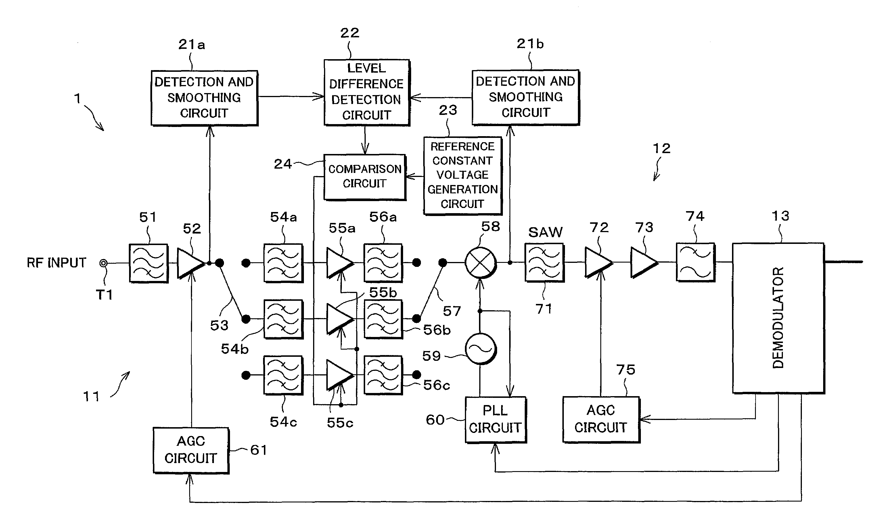
[0066]Referring to FIGS. 1 through 8, the following description will describe one embodiment of the present invention. That is, an automatic gain control circuit (AGC circuit) in accordance with the present embodiment is a circuit which can obtain a wide dynamic range of an input signal, and is particularly used appropriately in, for example, digital receivers and cable modems for ground wave TV and CATV, etc.

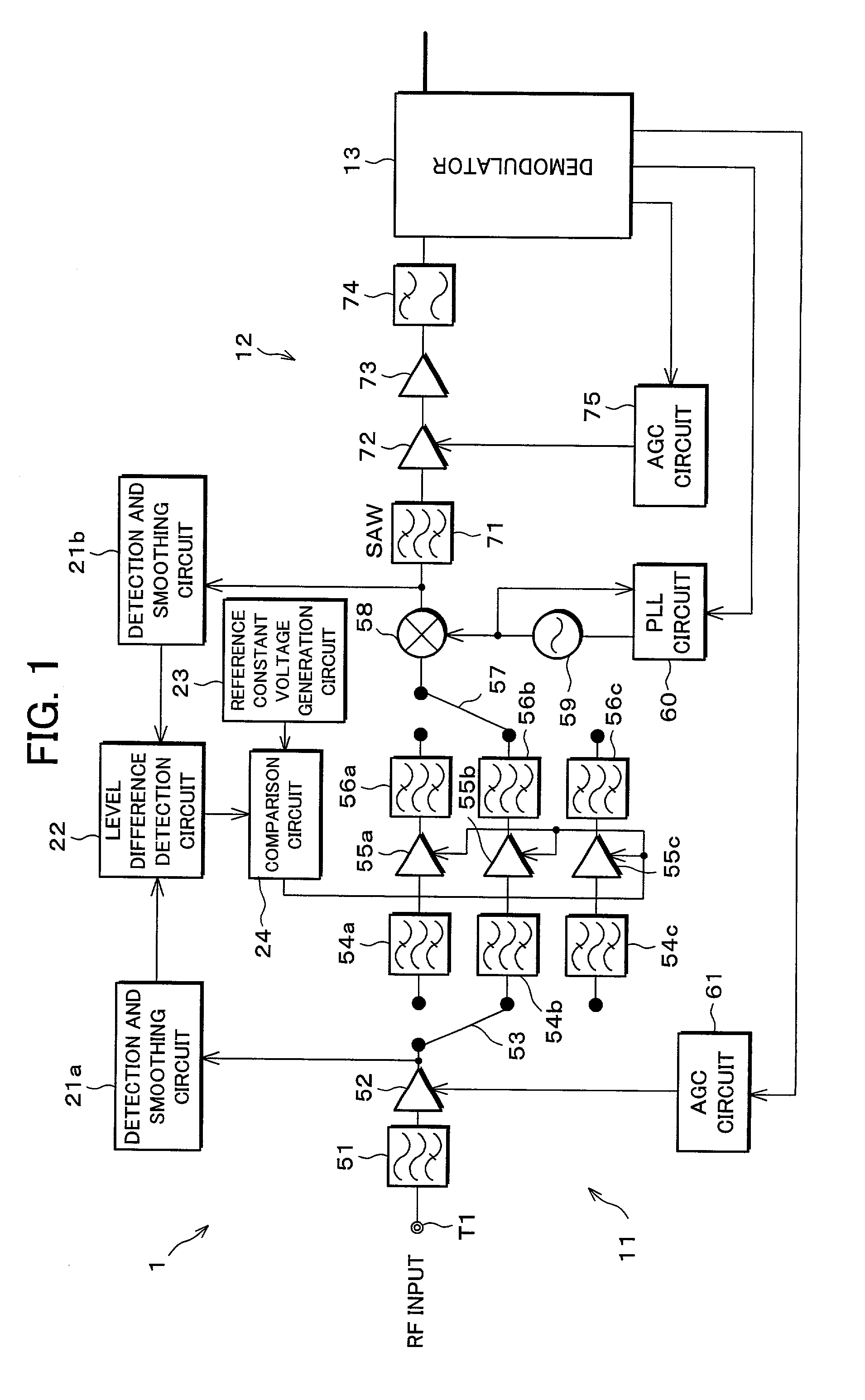
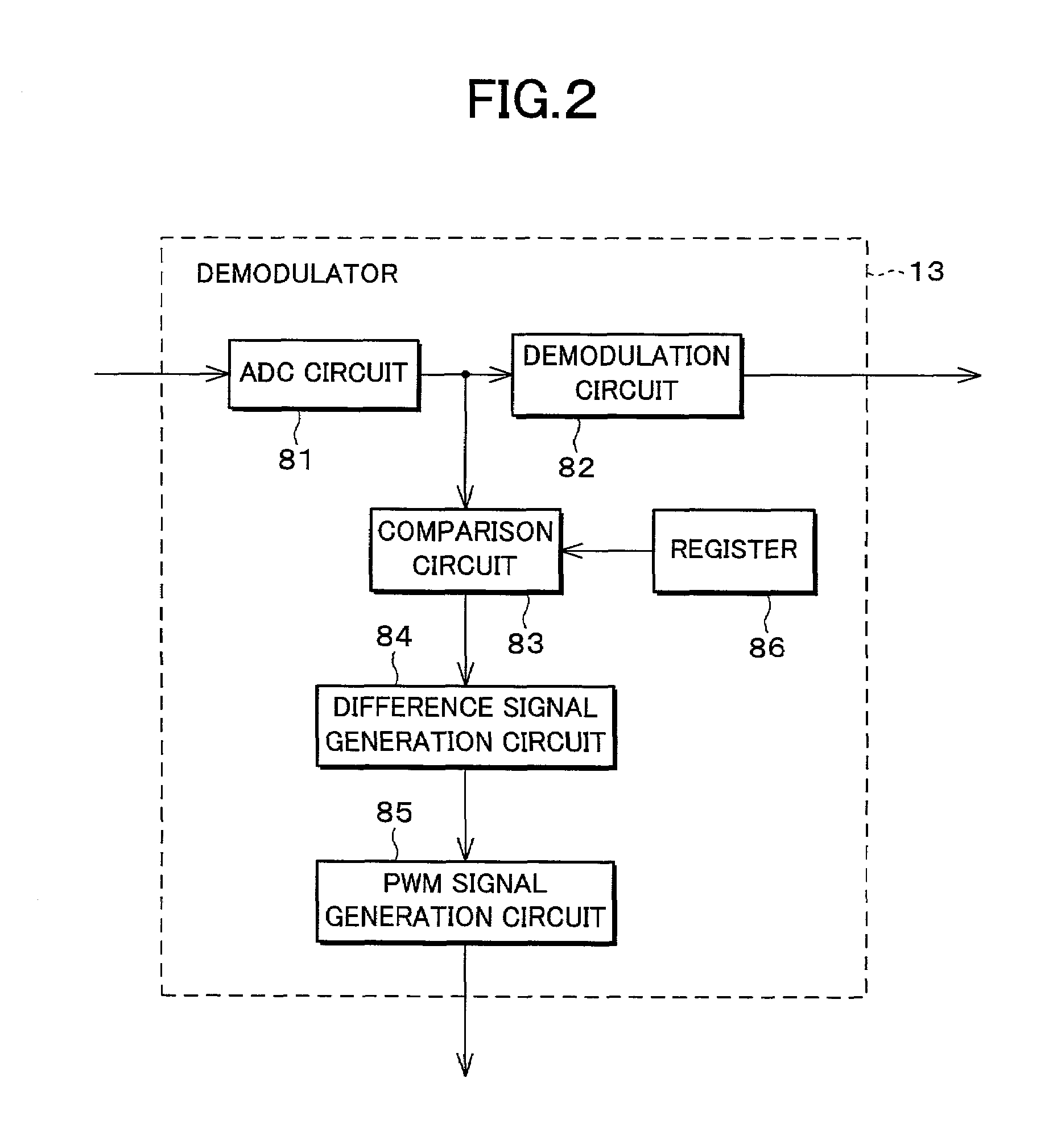
[0067]As one example, explanation will be given on a QAM (Quadrature Amplitude Modulation) receiver for digital CATV. As shown in FIG. 1, a digital receiver (automatic gain control circuit) 1 is structured so as to include a tuner section 11 which selects a signal of a desired channel among a QAM signal (RF input) inputted to an RF input terminal T1, and converts the signal to an intermediate frequency signal having an intermediate frequency, an intermediate frequency processing section 12 for amplifying the intermediate frequency signal, and a demodulator (co...

second embodiment

[Second Embodiment]

[0098]In the first embodiment, explanation has been given on a case where the gain is controlled by the RF-AGC amplifiers 55a to 55c, assuming a structure of a general tuner, that is, a structure in which the RF-AGC amplifiers 55a to 55c whose gains can be adjusted from the outside are already provided in the tuner section 11.

[0099]On the other hand, in a digital receiver 1a in accordance with the present embodiment, as shown in FIG. 9, an IF-AGC amplifier 76 is provided instead of the IF amplifier 73, and the demodulator 13 controls a gain of the IF-AGC amplifier 76. Further, the comparison circuit 24 controls a gain of the IF-AGC amplifier 72 instead of the gains of the RF-AGC amplifiers 55a to 55c. Incidentally, along with these changes, the RF-AGC amplifiers 55a to 55c are changed to RF amplifiers 62a to 62c whose gains are fixed. In this structure, the IF-AGC amplifier 76 corresponds to second gain control means, and the IF-AGC amplifier 72 corresponds to thi...

third embodiment

[Third Embodiment]

[0103]In the present embodiment, explanation will be given on a case where a PIN diode attenuator is used to adjust the gain of the tuner section 11. Incidentally, this structure can be applied either of the foregoing first and second embodiments, but the following explanation will be given on a case where this structure is applied to the first embodiment.

[0104]That is, as shown in FIG. 10, in a digital receiver 1b in accordance with the present embodiment, an RF amplifier 63 and a PIN diode attenuator 64 are provided instead of the RF-AGC amplifier 52 shown in FIG. 1, and the demodulator 13 controls a gain of the PIN diode attenuator (first gain control means) 64 by the AGC circuit 61. Besides, in the present embodiment, dual-gate FETs (Field-Effect Transistors) are used in the RF-AGC amplifiers 55a to 55c for gain control.

[0105]Here, the PIN diode attenuator 64 is a passive element, and is superior in frequency characteristics, compared with a case where gain adj...


PUM


Abstract

A demodulator controls gains of an RF-AGC amplifier and an IF-AGC amplifier so as to maintain an input level to the demodulator constant. In this case, the demodulator estimates a signal level of an RF input based on the sum of the gains directed to the both AGC amplifiers, and changes methods for distributing a gain to the AGC amplifiers, according to whether or not the signal level exceeds a predetermined Take Over Point. Further, a first detection and smoothing circuit detects an output level of the RF-AGC amplifier, and a second detection and smoothing circuit detects an output of a mixer. Besides, a comparison circuit controls the gain of the RF-AGC amplifier so that a difference between the output levels comes to be a predetermined value. With this structure, an automatic gain control circuit which can achieve high receiving sensitivity and low waveform distortion simultaneously can be realized even when manufacturing dispersion is caused.

Description

FIELD OF THE INVENTION[0001]The present invention relates to an automatic gain control method and an automatic gain control circuit appropriately used in a receiver having a wide input dynamic range, for example, such as a cable modem.BACKGROUND OF THE INVENTION[0002]For example, as shown in FIG. 18, in a conventional digital receiver 101, a tuner section 111 selects a signal of a desired channel from an RF (radio frequency) input, and converts the signal to an intermediate frequency signal having an intermediate frequency, and an intermediate frequency processing section 112 amplifies the intermediate frequency signal, then a demodulator 113 demodulates the intermediate frequency signal and takes out a baseband signal. Besides, the tuner section 111 and the intermediate frequency processing section 112 are provided with AGC (Automatic Gain Control) amplifiers 155 and 172, respectively, whose gains can be adjusted, and the demodulator 113 controls the gains of the AGC amplifiers 155...

Claims


Application Information

Patent Timeline
Patent Type & Authority Patents(United States)
IPC IPC(8): H04L27/38H03G3/20H03G3/30H04B1/16H04B1/26
CPCH04L27/3809
Inventor KOIZUMI, HARUO
Owner SHARP KK
Why Eureka
Try Eureka