Transreflector antenna for wireless communication system

a technology of wireless communication system and reflector antenna, which is applied in the direction of transmission, broadcasting with distribution, substation equipment, etc., can solve the problems of increasing the amount of interference from one hub to the other, complex cell layout, and the design of lmds systems

Inactive Publication Date: 2005-11-15
GOOGLE LLC
View PDF4 Cites 176 Cited by
  • Summary
  • Abstract
  • Description
  • Claims
  • Application Information

AI Technical Summary

Benefits of technology

[0009]Briefly, the present invention is a compact, lightweight, inexpensive antenna for use with wireless communication services including, but not limited to, line of sight microwave frequency services such as Local Multipoint Distribution Services (LMDS).
[0010]The antenna provides for transmission and reception on a vertical and / or horizontal plane as well as isolation for cross-polarized components. The design provides for precise control over isolation and polarization characteristics.
[0022]This arrangement provides a low cost, minimum part count, low profile, easy to manufacture antenna for use in line of sight, full duplex microwave signaling applications.

Problems solved by technology

However, the designers of LMDS systems are faced with several challenges at the present time.
Because such systems send very high frequency radio signals over short line-of-sight distances, cell layout has proven to be a complex issue.
Also, narrow sectors using the same polarization increase the amount of interference from one hub to the other.
However, the design of antennas with low cross-polarization levels throughout the sector remains a challenge.
Another challenge is in the electronics technology needed to implement the service.

Method used


Image

  • Transreflector antenna for wireless communication system
  • Transreflector antenna for wireless communication system
  • Transreflector antenna for wireless communication system

Examples


Embodiment Construction

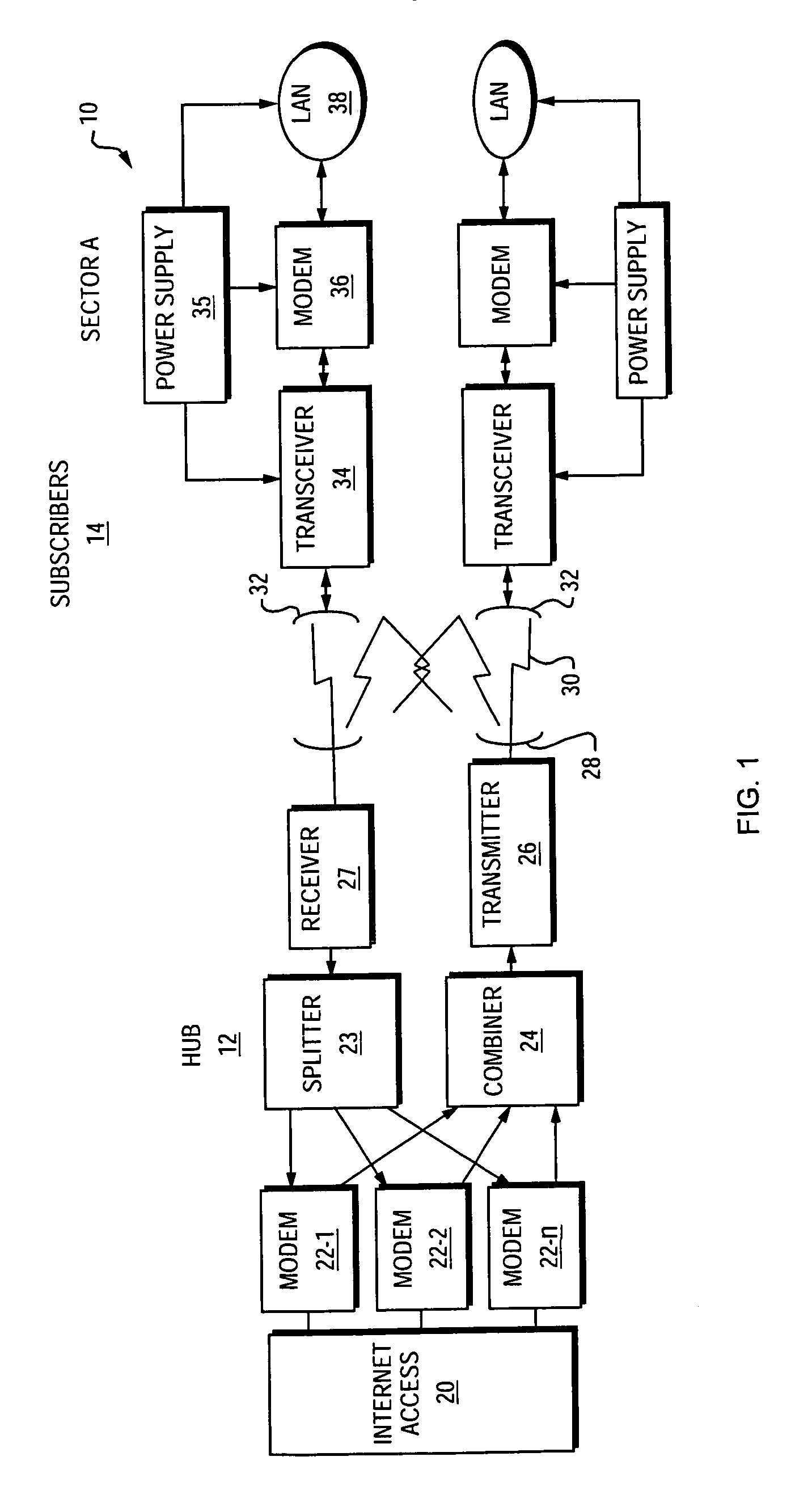
[0030]FIG. 1 is a block diagram of a system 10 for providing a high speed direct line of sight wireless data service such as Local Multipoint Distribution Service (LMDS) using millimeter-wave frequency radio signals for a physical layer medium. The system 10 consists of equipment at a hub location 12 as well as equipment at multiple subscriber locations 14. It should be understood that the subscriber units 14 may individually be located in a particular sector of a cell to provide support for a greater number of subscribers within a given cell using a limited number of carrier frequencies. In the illustrated system 10, multiple subscribers are provided with a high speed data service to provide access to the Internet.

[0031]The equipment at the hub 12 consists of a connection to a point-of-presence (POP) into the network or other Internet access device 20, and multiple modems 22-1, 22-2, 22-n. In the transmit (e.g., forward link) direction, the modems 22 convert baseband digital signal...


PUM


Abstract

A compact lightweight antenna for receiving microwave direct line of sight wireless data signals used in services such as Local Multipoint Distribution Services (LMDS). The antenna provides for precise control over isolation of polarized signals. The antenna consists of an external parabolically shaped dome formed of a suitably resilient material such as thermoplastic. A polarizing conductive grating is formed on the interior surface of the dome and serves as a transreflector for initially passing received radiation having a vertical polarization. A twist reflector disposed at a point along an axis defined by the conductive grating reflects the received radiation, back in the direction of the transreflector with a different polarization. The now differently polarized energy is reflected by the parabolically shaped conductive grating at a feed point located in the center of the twist plate. The transreflecting element may be manufactured by providing a substrate that has been printed and etched and / or a film nonconductive substrate which has been silk screened with a conductive ink. In each of these cases in a preferred embodiment, the substrate or carrier film becomes an integral part of the mold in the resulting article.

Description

RELATED APPLICATION(S)[0001]This application is a continuation-in-part of a prior U.S. patent application Ser. No. 09 / 317,767, filed May 24, 1999 now U.S. Pat. No. 6,370,398, entitled “Transreflector Antenna For Wireless Communication System.” The entire teachings of the above application(s) are incorporated herein by reference.BACKGROUND OF THE INVENTION[0002]There continues to be ever increasing demand for distributed high speed access to computer networks such as the Internet and private networks. Competition is fierce among various schemes which rely upon wires for physical layer connectivity, such as T1 carrier, Digital Subscriber Line (xDSL), cable modem, fiber optic distributed data interface (FDDI), and the like. However, it is readily apparent that wireless access systems continue to hold the promise of reducing network buildout costs, especially in areas where telephone, cable and / or fiber optic lines are not yet installed. Wireless systems almost always promise the most r...

Claims


Application Information

Patent Timeline
Patent Type & Authority Patents(United States)
IPC IPC(8): H01Q19/10H01Q1/42H01Q19/195H01Q15/12H01Q19/06
CPCH01Q1/425H01Q19/195H01Q15/14
Inventor KANAMALURU, SRIDHARWOOD, KENNETH R.
Owner GOOGLE LLC
Why Eureka
Try Eureka