Ridge vent for tile roofs

a technology for ridge vents and tile roofs, applied in ventilation systems, lighting and heating apparatus, heating types, etc., can solve the problems of significant additional assembly steps, significant additional costs, and significant increases in time, cost and effort associated with installing ridge vents for tile roofs, and achieves reduced installation time, high strength, and low cost.

Inactive Publication Date: 2005-11-22
DIXON DAVID J
View PDF39 Cites 23 Cited by
  • Summary
  • Abstract
  • Description
  • Claims
  • Application Information

AI Technical Summary

Benefits of technology

[0009]The above and other objects are provided by a ridge vent in accordance with a preferred embodiment of the present invention. The ridge vent of the present invention generally comprises a main body portion having a pair of oppositely extending eaves, a neck portion and a pair of oppositely extending flanges. The eaves each have a plurality of slots formed therein for allowing air to enter and exit the ridge vent once it is installed on a roof. The ridge vent forms a one-piece component which is extremely lightweight, relatively inexpensive to produce and, most importantly, completely eliminates the need for installing a nailer board on at the ridge of the roof before installing the ridge vent.
[0010]The ridge vent of the present invention is installed by positioning it over an opening formed at the ridge of a roof. The flanges are then secured by threaded screws or nails to the roof. The neck portion spaces the main body portion a short distance above the roof while the slots in the eaves allow air to circulate into and out from the ridge vent. Since no nailer board is required to support any portion of the ridge vent, installation time is significantly reduced. A ti

Problems solved by technology

The requirement for a nailer board (i.e., either a 2×4 or 2×6) thus represents a significant additional assembly step, as well as a significant additio

Method used


Image

  • Ridge vent for tile roofs
  • Ridge vent for tile roofs
  • Ridge vent for tile roofs

Examples


Embodiment Construction

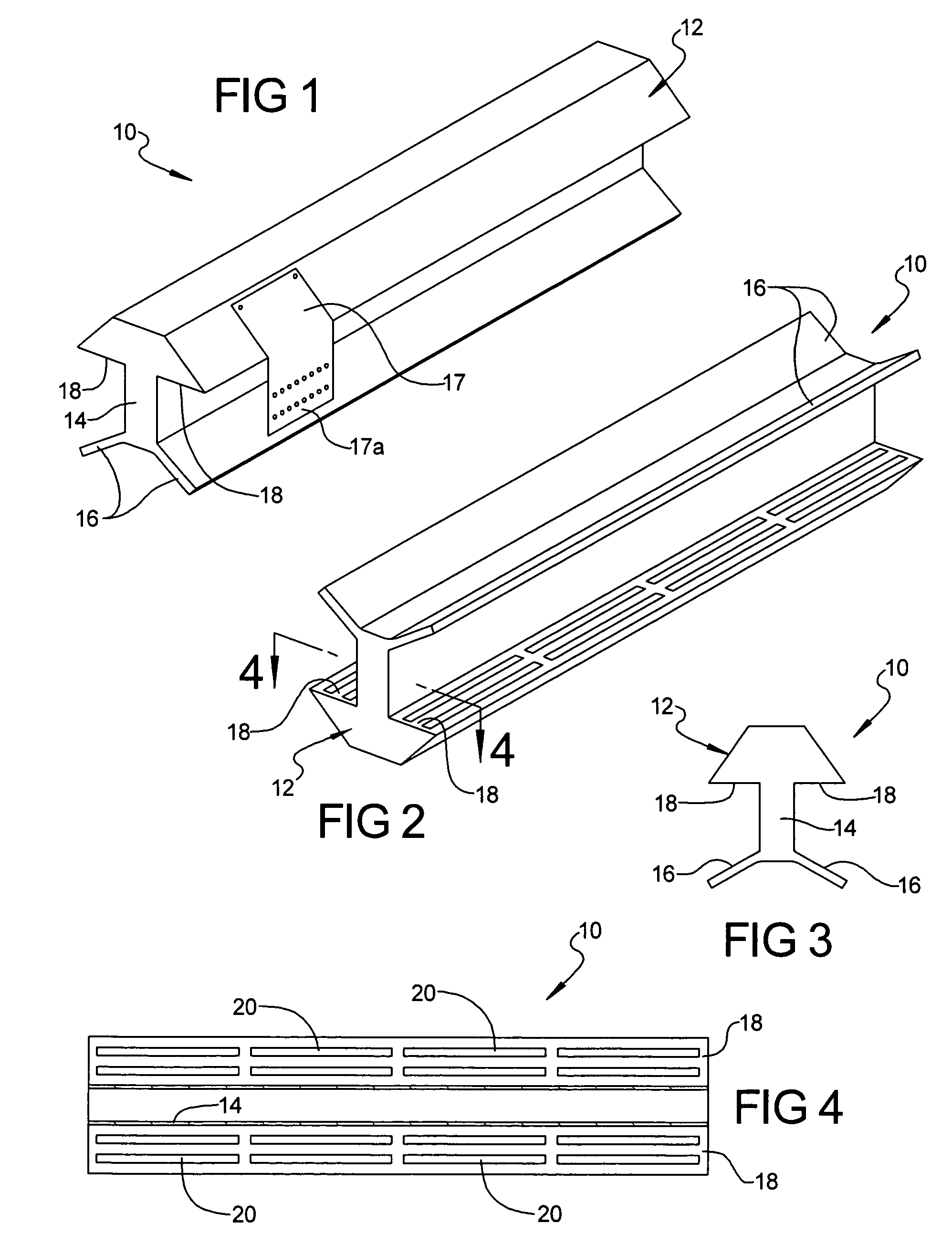
[0029]Referring to FIG. 1, there is shown a ridge vent 10 specifically adapted for use with tile roofs. The ridge vent 10 may be made from metal, plastic, aluminum or any other suitable, lightweight material or sheet metal. The ridge vent 10 generally comprises a main body portion 12 forming a hollow area therewithin, a hollow neck portion 14 and a pair of flanges 16 which depend from the neck portion 12 and which flare outwardly away from each other.

[0030]Referring to FIGS. 2 and 3, the main body portion 12 includes a pair of eaves 18 each having a plurality of slots 20 formed therein. While eight slots 20 are shown formed in each eave 18, it will be appreciated that the number of slots could vary significantly depending upon the overall dimensions of the ridge vent 10 or the desired degree of airflow therethrough. Optionally, as shown in FIG. 1, a cover 17 having a plurality of openings 17a could be secured to the main body portion 17 to ensure that the slots 20 are blocked from v...


PUM


Abstract

A ridge vent adapted specifically for use with tile roofs having a nailer board installed at a ridge of a roof. The ridge vent includes a main body portion having a pair of eaves and a neck portion. The neck portion includes a plurality of projections on opposing inner walls thereof to maintain a minimum predetermined spacing between the inner walls and the nailer board, to thereby create airflow paths around opposing sides of the nailer board. A pair of weather blocking panels are secured to the nailer boards to help block rain, snow, etc. from entering though openings in the eaves. Each weather blocking panel includes a laterally extending portion with a plurality of slots and an upwardly extending edge portion. The upwardly extending edge portion creates a venturi effect over the slots to help draw air out therethrough when wind is blowing over the upwardly extending edge portions. The weather blocking panels may be formed with finger-like projections or arcuate shaped cutouts, depending on the specific contour of the roof tiles used on the roof to which the ridge vent is attached.

Description

CROSS REFERENCE TO RELATED APPLICATIONS[0001]This application claims priority from U.S. Ser. No. 60 / 365,018 filed Mar. 15, 2002, presently abandoned.FIELD OF THE INVENTION[0002]This invention relates to roof vents for residential or commercial dwellings, and more particularly to a roof vent specifically adapted for use with tile covered roofs.BACKGROUND OF THE INVENTION[0003]Tile roof ridge vents are typically used to vent an attic area of a residential or commercial dwelling, which area can become extremely hot during summer months. Typically, existing tile roof ridge vents require a nailer board, which is usually a 2×4 or 2×6 stud, to be secured to the trusses along the ridge such that the stud stands up and forms a surface to which the ridge vent can be secured. The ridge vents are usually two or three piece components which have a pair of flanges flaring outwardly away from each other. The flanges are adapted to be nailed to the roof. A cap portion of the ridge vent is then nail...

Claims


Application Information

Patent Timeline
IPC IPC(8): E04D13/00E04D13/17F24F7/02
CPCE04D13/174F24F7/02
Inventor DIXON, DAVID J.
Owner DIXON DAVID J
Why Eureka
Try Eureka