
Systems and methods for controlling local environment

a technology of local environment and control system, applied in the direction of dust-free enclosures, humidity control, carburettors, etc., can solve the problems of difficult to provide controlled boiling that generates the required amount of water vapor, the complex process of boiling water at the steam source is unstable, and the coupling between temperature and relative humidity presents challenges in the design of the closed-loop controller

Inactive Publication Date: 2005-11-22
ASML HLDG NV
View PDF42 Cites 23 Cited by
  • Summary
  • Abstract
  • Description
  • Claims
  • Application Information

AI Technical Summary

Benefits of technology

[0010]The present invention provides a robust and cost-effective alternative to the systems used previously because final humidity and temperature can be treated as decoupled parameters.
[0012]In a preferred embodiment, the system avoids the difficulty of controlling coupled temperature and humidity outputs. In an air-water system, the thermodynamics of moist air dictates the dry bulb and saturation temperatures of the air determine its relative humidity. With the use of steam tables, the problem of controlling temperature and relative humidity can be transformed into one of controlling dry bulb and saturation temperature. Because there is no direct coupling in the control of these parameters, the invention permits precise control of local environments used in the ULSI technology.

Problems solved by technology

The coupling between temperature and relative humidity presents challenges to the design of the closed-loop controller.
However, boiling water at the steam source is an unstable complex process, and it is difficult to provide controlled boiling that generates the required amount of water vapor to control humidity within the required tolerances ±0.5% RH.
Furthermore, the response time of humidity levels resulting from change in the heater power supply is too slow and unpredictable.
Because the temperature and relative humidity are coupled and it is difficult to precisely controlling the amount of steam used to humidify the air, this conventional approach has significant drawbacks.

Method used


Image

  • Systems and methods for controlling local environment
  • Systems and methods for controlling local environment
  • Systems and methods for controlling local environment

Examples


Embodiment Construction

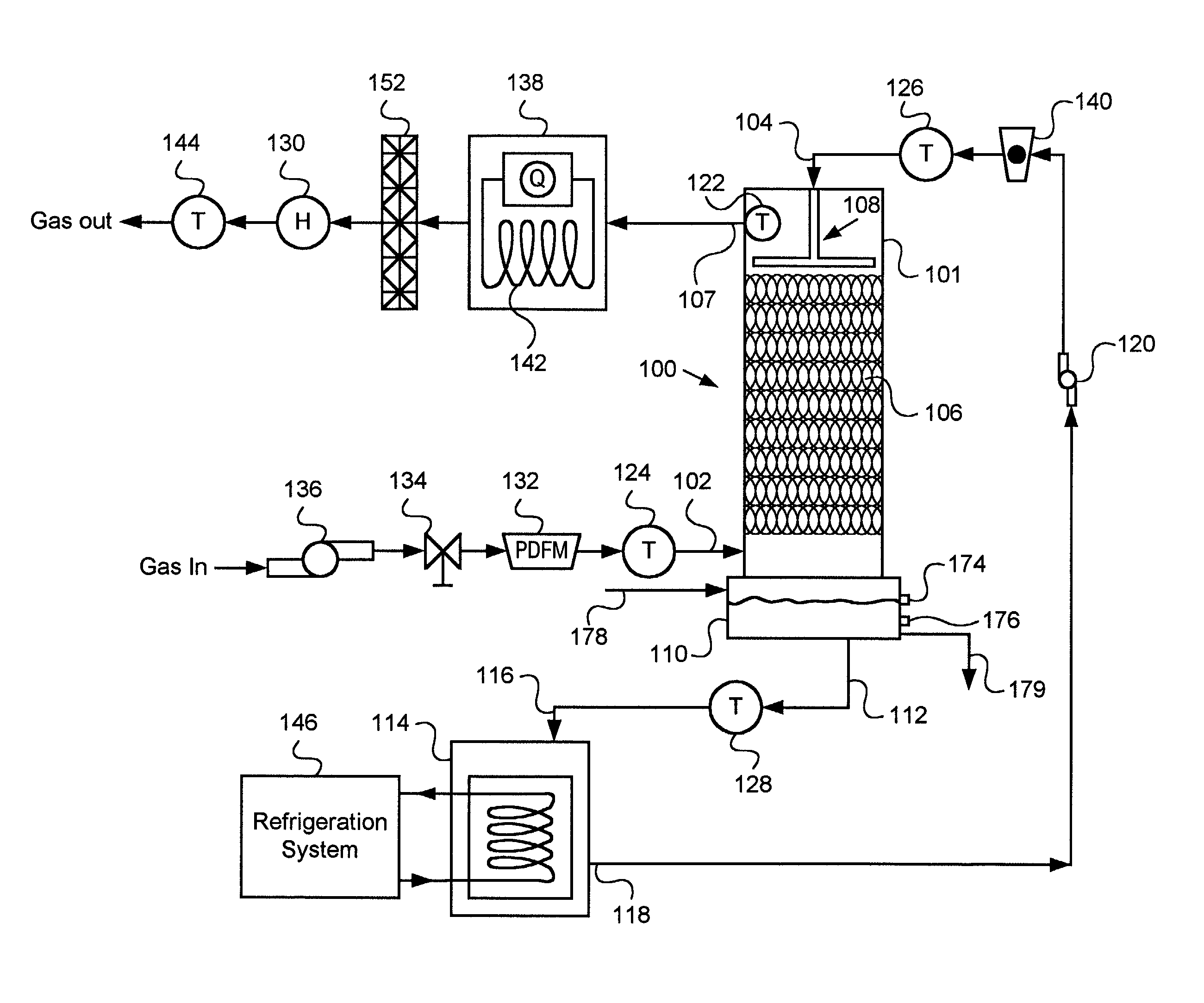
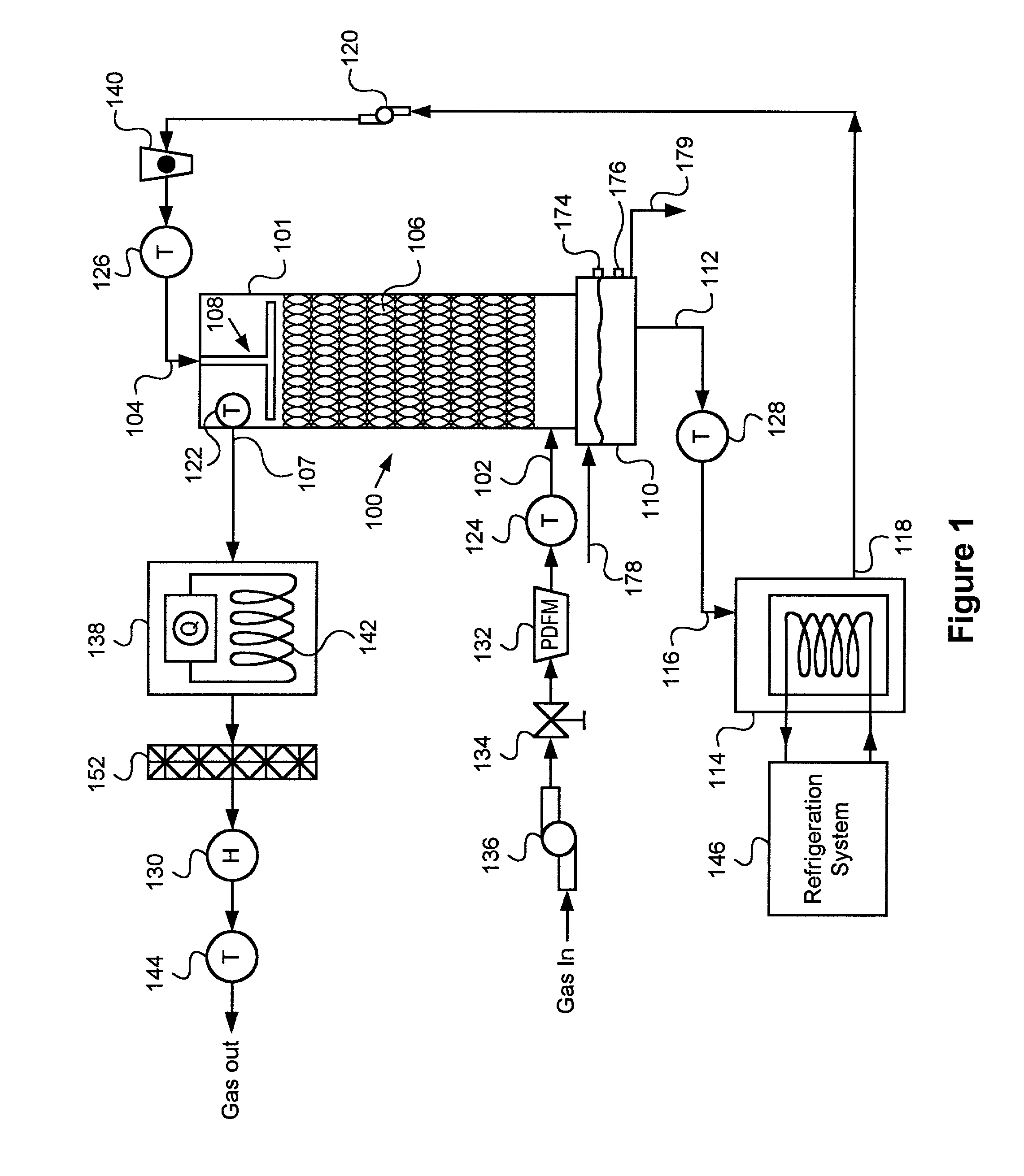
[0026]The present invention relates to a system for controlling the local environment of a gas-liquid system. In a preferred embodiment, the system uses a gas-liquid contactor 100 for humidifying or dehumidifying the gas. As shown in FIG. 1, the gas-liquid contactor 100 includes a housing filled with a contact media 106, a gas inlet 102 below the contact media 106, a gas outlet 107 above the contact media 106, a liquid sprinkler 108 above the contact media 106, and a liquid reservoir 110 below the housing with an outlet 112.

[0027]In a preferred embodiment, the gas-liquid contactor 100 is a direct-contact cooler condenser that operates like a cooling tower, but instead the liquid is heated and the gas is cooled. The governing equations and solutions are similar. Cooling tower theory is dealt with by Mills & Irwin, Heat and Mass Transfer (1995), which is incorporated by reference.

[0028]In a preferred embodiment, the contact media 106 is material with a large surface area / volume of mat...


PUM

PropertyMeasurementUnit
Lengthaaaaaaaaaa
Lengthaaaaaaaaaa
Lengthaaaaaaaaaa

Abstract

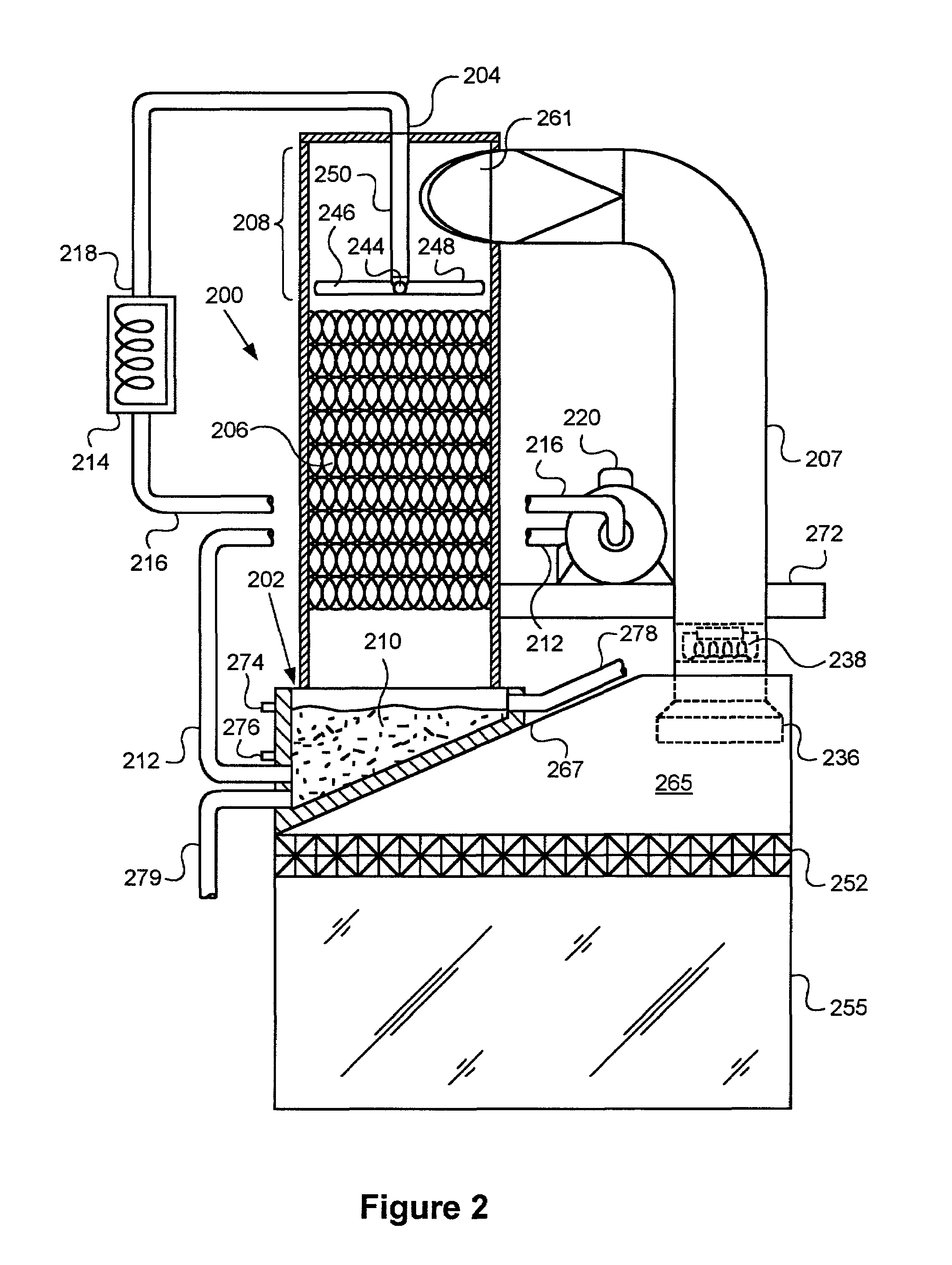
The present invention provides systems and methods of controlling local environment. In one embodiment, incoming air enters a contactor such the Direct Contact Cooler-Condenser (DCCC) where the air contacts water distributed on the contact media. After passing through the DCCC, the air is saturated at a temperature equal or close to that of the water. Depending on the state of the incoming air, in the DCCC will be humidified or dehumidified to yield saturated air at the desired humidity ratio. In one embodiment, a blower draws air through the DCCC and blows into the heater. The heater heats the air to the desired dry-bulb temperature. Before exiting, the air may pass through a filter.

Description

[0001]The present invention relates in general to the control of local environment, and in particular, to systems and methods for controlling the temperature, humidity, and cleanliness of gas such as air delivered to semiconductor equipment.BACKGROUND OF THE INVENTION[0002]There are many applications in semiconductor manufacturing where tight control of temperature, relative humidity, and particles of a process gas such as air becomes critical. See Chang & Sze, ULSI Technology (1996), which is hereby incorporated by reference.[0003]Foundries, including metrology, lithography, and track areas where photoresist and developer is applied to silicon wafers, may require air having a relative humidity of 45%±0.5% at 24±0.1 C, while other cleanroom areas may require a relative humidity of 45%±5% at 24±0.5 C. For example, the humidity of air delivered to a photoresist spin station must be controlled because it affects the evaporation rate of solvent of the resist. To avoid particle contamina...

Claims


Application Information

Patent Timeline
IPC IPC(8): F24F5/00
CPCF24F5/0035F24F2006/006Y02B30/545Y02B30/54H01L21/00
Inventor BABIKIAN, DIKRAN S.WADE, BRYAN H.
Owner ASML HLDG NV
Learn More