Solar cell module and roof equipped with power generating function using the same

a solar cell module and power generation function technology, applied in the direction of electrochemical generators, light radiation electric generators, batteries, etc., can solve the problems of solar cell module failure, sleeve setting portion water leakage, execution efficiency deterioration, etc., to prevent water leakage effectively and smooth cable extension

Inactive Publication Date: 2005-11-22
KANEKA CORP
View PDF28 Cites 59 Cited by
  • Summary
  • Abstract
  • Description
  • Claims
  • Application Information

AI Technical Summary

Benefits of technology

[0051]In the case of the above roof equipped with a power-generating function, it is possible to smoothly extend the cable guided by the sleeve on the roof with no resistance. Moreover, because the cable exit introduced into the indoor side opens on...

Problems solved by technology

However, because rainwater may enter the backside of the module when rain and wind are strong.
Thereby, the problem of water leaked into the inside of a house occurs at the portion 102a or face 102b due to a long-times stay of the rainwater or stayed moisture may cause a failure of the solar cell module 101 because the air permeability of the backside of the module is not sufficiently maintained.
In this case, however, a trouble may occur that the output cable 141 is held between the adiabatic support member 102 and roof body...

Method used


Image

  • Solar cell module and roof equipped with power generating function using the same
  • Solar cell module and roof equipped with power generating function using the same
  • Solar cell module and roof equipped with power generating function using the same

Examples


second embodiment

[0112]Then, second embodiment of the present invention is described below by referring to FIG. 12. In the case of the solar cell module 1A of this embodiment, a concave portion 23 is formed on the setting position of a terminal box 42 instead of a pair of adiabatic support members 2 and 2 set to the both sides of the terminal box 42 at the backside of a solar cell 5 and a horizontal rectangular adiabatic support member 2A integrally molded over the both sides of the terminal box 42 is provided. Moreover, bottomed drain ditches 3A, . . . opening on the contact face to a roof body are formed on the adiabatic support member 2A so as to cross vertically and horizontally and communicate with the lateral side of the adiabatic support member 2A and output cables 41 and 41 extended from the terminal box 42 are temporarily and removably fixed in a drain ditch 3A until the solar cell module 1A is set on a roof body as illustrated and when drainwater enters the backside of the solar cell modul...

third embodiment

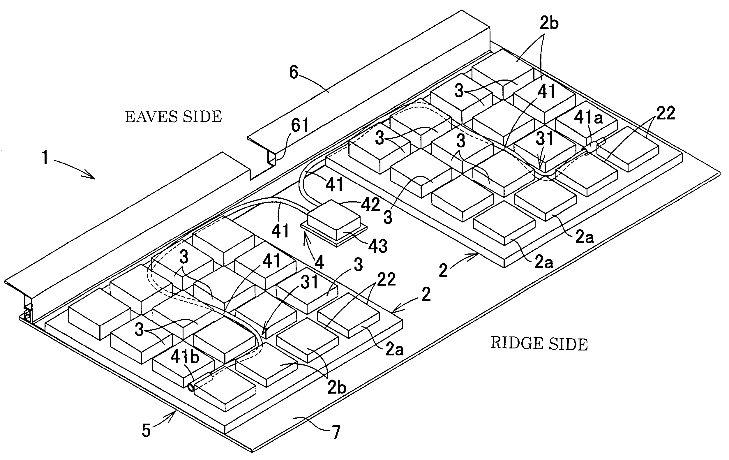
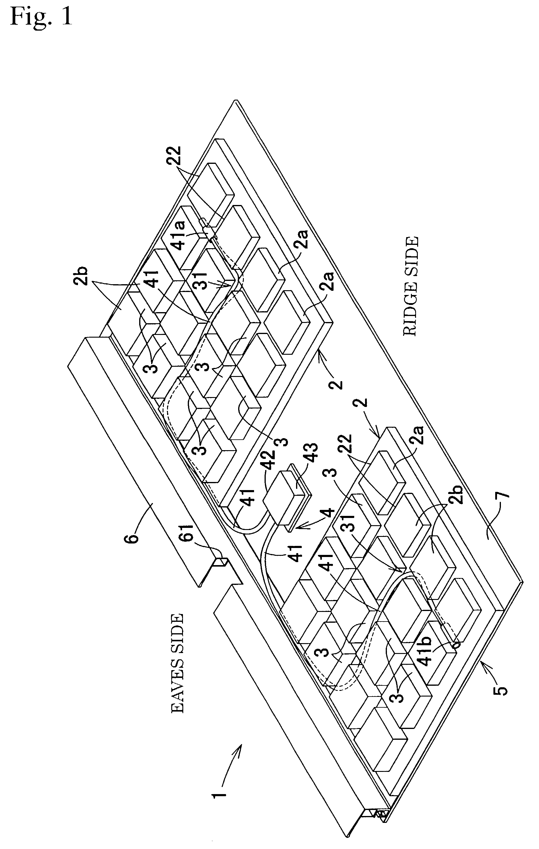
[0114]Then, third embodiment of the present invention is described below by referring to FIGS. 13 to 18. As shown in FIG. 13, the solar cell module 1B of this embodiment is provided with a solar cell 5 constituting a roof member, output cables 41 and 41 extended from the backside of the solar cell, and an adiabatic support member 2 fixed to the backside of the solar cell 5 and contacting the surface of a roof body. The adiabatic support member 2 is constituted by a flat body portion 20 face-fixed to the backside of the solar cell 5 and a plurality of legs 21 . . . independent each other and vertically set to the roof body from the flat body portion 20.

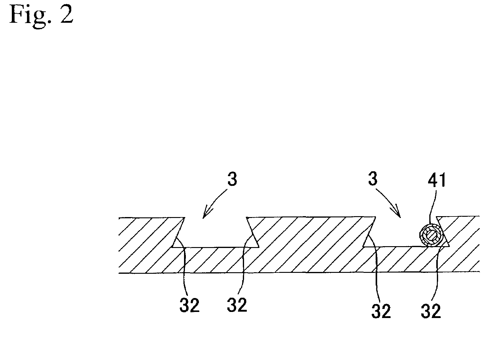
[0115]In the case of this embodiment, a cable-holding groove 30 opening at a contact face 2b to a roof body and having a depth larger than that of a cable diameter and holding an inserted output cable 41 while housing the cable 41 without protruding it from the opening is provided to at least one leg selected out of the legs 21, . . . ...

fifth embodiment

[0130]Then, fifth embodiment of the present invention is described below by referring to FIGS. 20 to 26. As shown in FIG. 20, the solar cell module 1D of the present invention is a building-material-integrated solar cell module provided with a solar cell 5 constituting a roof member and a support table 6 for supporting the solar cell to fix it to a roof body 10, in which a plurality of geta members 9, . . . are arranged at the bottom 6a of the support table 6 facing the roof body 10. Thus, because the present invention is provided with the geta member 9 for floating the support table 6 from the roof body 10, rainwater is smoothly discharged through a water channel 19b of the verge-substrate dewatering eaves 19 without crushing a bent portion 19a for stopping the rainwater when setting the solar cell module 1D to the upper side of a verge-substrate dewatering eaves 19 so as to cover the eaves 19 as shown in FIG. 26.

[0131]The applicable range of the geta member 9 described for this em...


PUM


Abstract

An object of the invention is to provide a solar cell module in which sufficient drainage and ventilation are ensured on the rear side, an output cable can be prevented from being caught during installation, and long term reliability is ensured by preventing bleed of the output cable, and another object of the invention is to provide a solar cell module integrated with building materials in which water leakage into the house and failure due to staying moisture can be avoided by imparting a waterproof function of a verge substrate water drip. A bottomed drain gutter opening to the abutting face of a heat insulating supporting material is provided to communicate with the side of the heat insulating supporting material, and a cable holding groove opening to the abutting face of a leg vertically provided on the heat insulating supporting material and deeper than the diameter of the laid cable is made to communicate with the side of the leg in order to hold the cable without projecting the cable from the opening. Furthermore, a plurality of geta members are arranged on the bottom of a supporting base and the thickness of each geta member is so set that the supporting base does not collapse the verge substrate water drip when the solar cell modules are laid on the verge substrate water drip.

Description

CROSS REFERENCE TO RELATED APPLICATIONS[0001]This application is a continuation of PCT Application No. PCT / JP01 / 02549, filed Mar. 28, 2001, which application was not published in English under PCT Article 21(2), and both the present application and the counterpart PCT application claim priority to Japanese Application Serial No. 2000-089268, filed Mar. 28, 2000, and Japanese Application Serial No. 2000-210593, filed Jul. 11, 2000.TECHNICAL FIELD[0002]The present invention relates to a solar cell module preferable for a solar power generation system and a roof equipped with a power generating function using the module, particularly to a solar cell module having an adiabatic support member contacting the surface of a roof body on the back of a solar cell and a roof equipped with a power generating function constituted by arranging the modules on a roof body.BACKGROUND ART[0003]A solar power generation system having been spread in recent years is constituted by a plurality of solar cel...

Claims


Application Information

Patent Timeline
IPC IPC(8): E04D3/40E04D13/18H01L25/00H01L31/04H01L31/00H01L31/048H02N6/00
CPCH02S20/23Y02B10/12Y10S136/291Y02B10/20Y02E10/50Y02B10/10
Inventor HATSUKAIWA, TERUKITOMITA, HIROHIKO
Owner KANEKA CORP
Why Eureka
Try Eureka