High temperature metallic seal

a high temperature, metallic seal technology, applied in the field of seals, can solve the problems of difficult to fabricate seal shapes with superior high temperature strength characteristics, limited long-term applications of current metallic seals, and difficult to meet the requirements of long-term use, and achieve the effect of cost-effective fabrication

Inactive Publication Date: 2005-11-29
PARKER INTANGIBLES LLC
View PDF9 Cites 32 Cited by
  • Summary
  • Abstract
  • Description
  • Claims
  • Application Information

AI Technical Summary

Benefits of technology

[0018]The resultant metallic composite structure can advantageously be fabricated cost effectively to provide complex creep/relaxation-resistant structures for ultrahigh temperature applications. Other high temperature formed st

Problems solved by technology

Therefore, long-term applications of current metallic seals are generally limited to about 1300° F. because the current cold formable nickel-based superalloys such as INCONEL 718 (Special Metals Corporation, Huntington, West Va.) and WASPALOY (Haynes International, Inc., Kokomo, Ind
These alloys can not readily be rolled into thinner gauges and cold formed into static seal shapes.
Recently developed mechanically alloyed strips such as MA 754 of Special Metals Corporation and PM 1000 of Plansee AG, Reutte, Aus

Method used


Image

  • High temperature metallic seal
  • High temperature metallic seal
  • High temperature metallic seal

Examples


Embodiment Construction

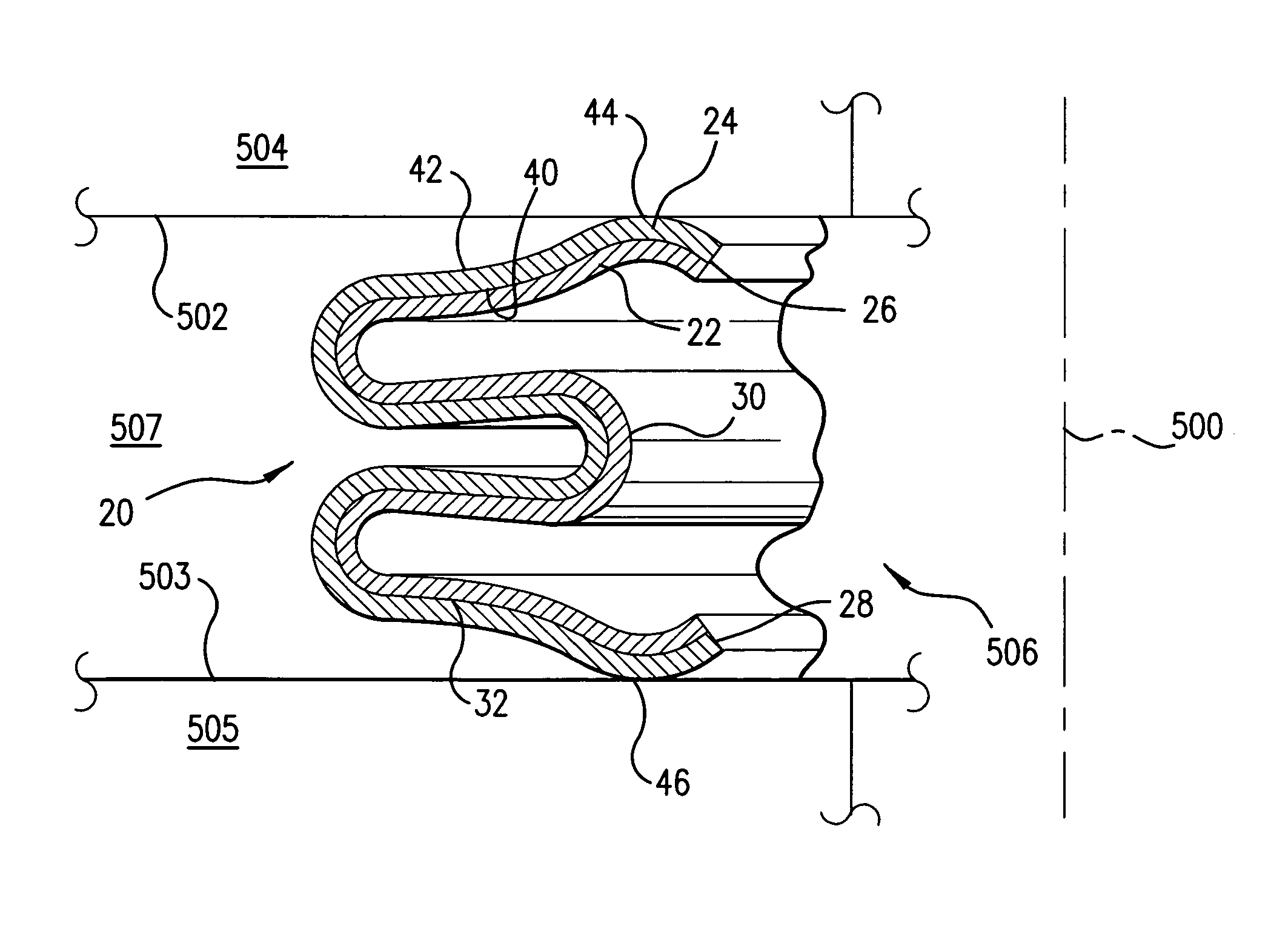
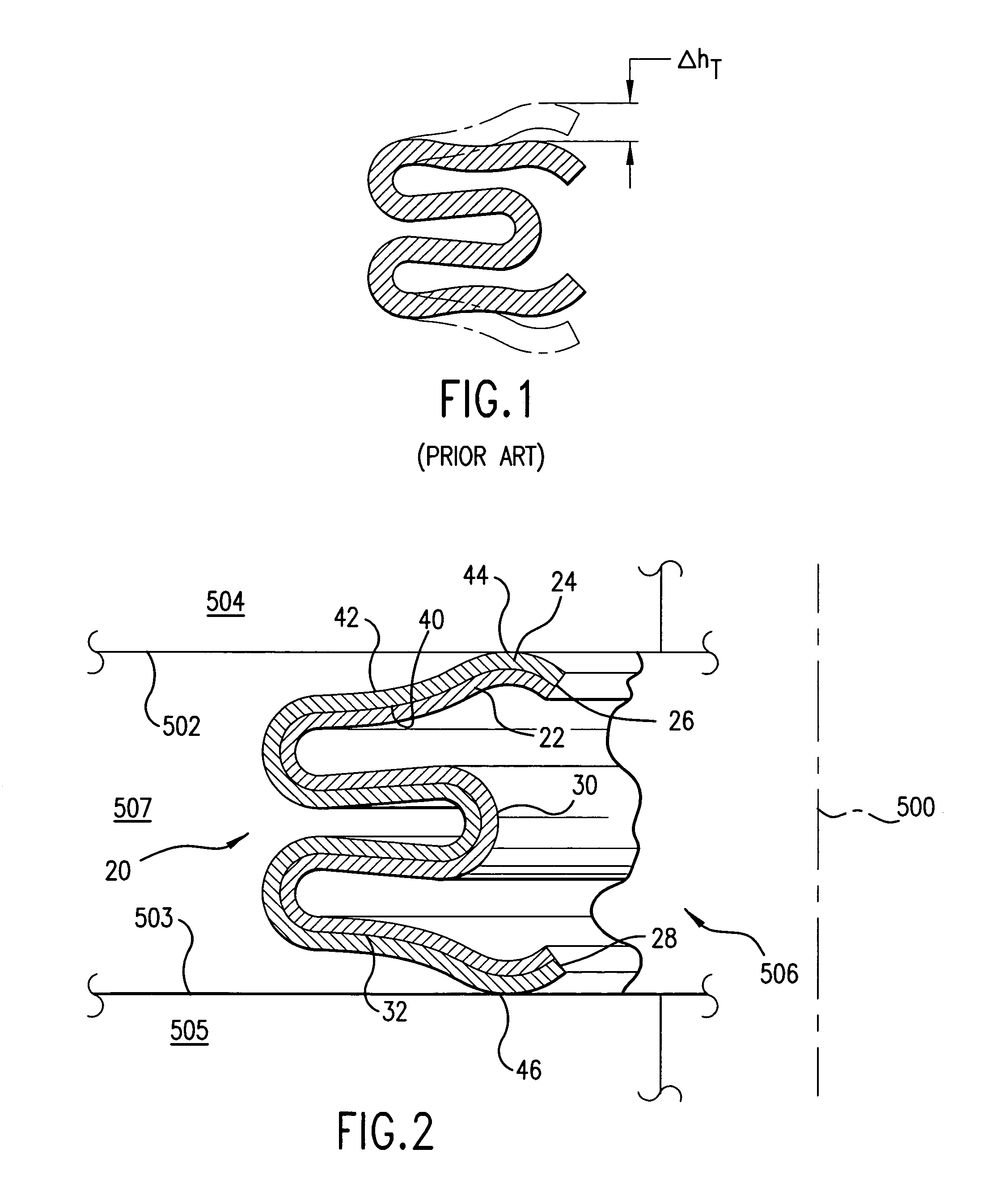
[0028]FIG. 2 shows a seal 20 formed as an annulus having symmetry about a central longitudinal axis 500. In operation, the seal is held in compression between opposed parallel facing surfaces 502 and 503 of first and second flanges 504 and 505 to isolate an interior volume 506 from an exterior volume 507.

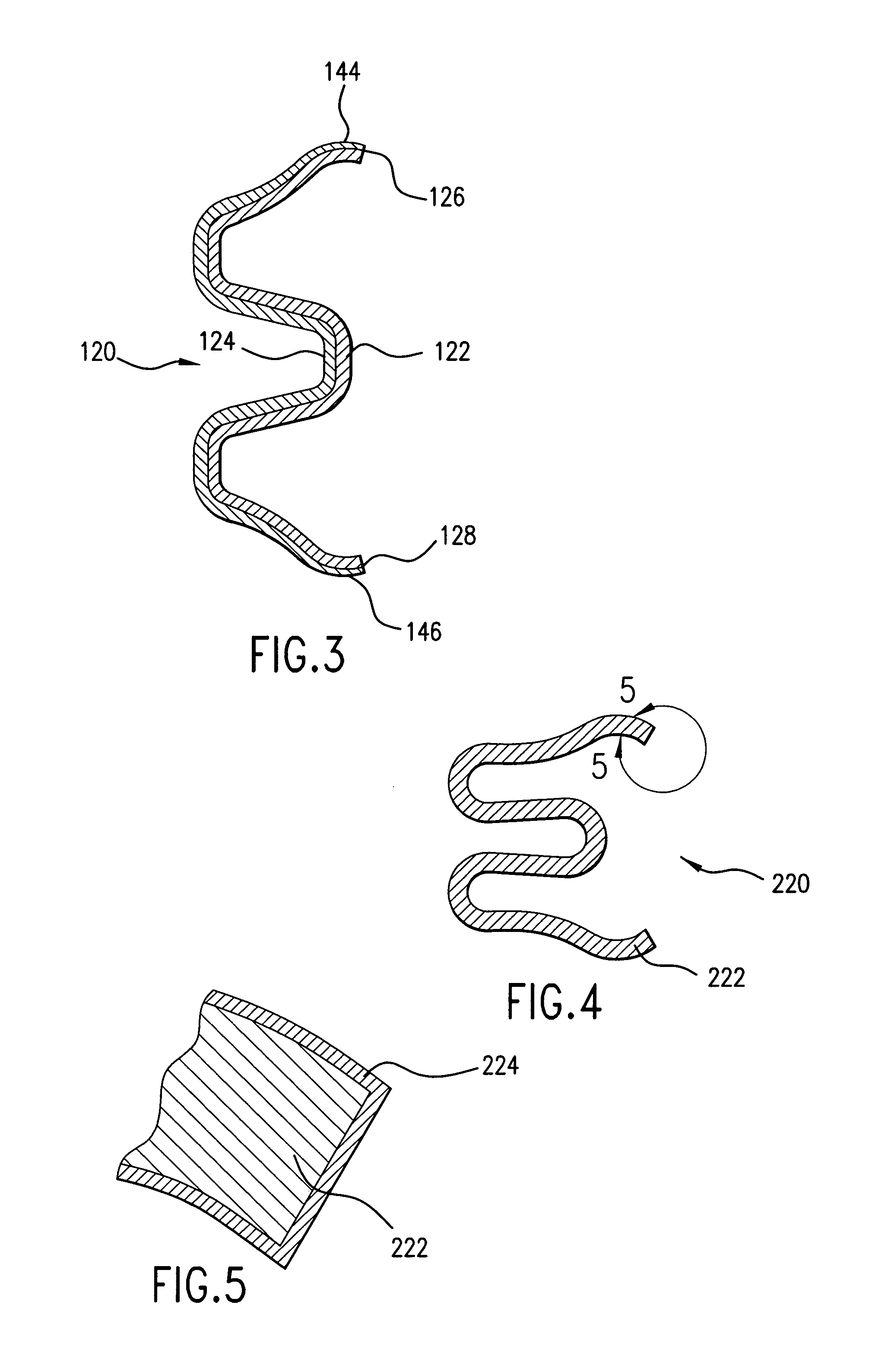
[0029]The seal is formed as a convoluted sleeve having first and second layers 22 and 24 and extending from a first end 26 to a second end 28. In the exemplary embodiment, the first layer 22 is generally interior of the second layer 24 and has first and second surfaces 30 and 32. In an exemplary manufacturing process, the first layer 22 is initially formed as a flat strip of cold formable material (e.g., it may be formed into a complex shape at a temperature which is less than half its Fahrenheit melting temperature and, preferably, at ambient conditions (room temperature)). The ends of the strip may be welded to form a sleeve, the two faces of the strip thereby becoming interior an...


PUM

PropertyMeasurementUnit
Temperatureaaaaaaaaaa
Fractionaaaaaaaaaa

Abstract

A metallic seal includes a cold formed substrate layer and one or more additional layers. At least one of the layers offers improved resistance to high temperature stress relaxation.

Description

CROSS-REFERENCE TO RELATED APPLICATIONS[0001]This application is a divisional application of U.S. patent application Ser. No. 10 / 002,684 (abandoned) filed Oct. 24, 2001 and entitled “HIGH TEMPERATURE METALLIC SEAL” which claims benefit of U.S. Provisional Patent Application Ser. No. 60 / 242,759 filed Oct. 24, 2000 and also entitled “HIGH TEMPERATURE METALLIC SEAL.” The disclosures of Ser. Nos. 60 / 242,759 and 10 / 002,684 are incorporated by reference herein as if set forth at length.BACKGROUND OF THE INVENTION[0002](1) Field of the Invention[0003]This invention relates to seals, and more particularly to metallic seals.[0004](2) Description of the Related Art[0005]A variety of metallic seal configurations exist. Key metallic seals are commonly held under compression between two opposed flanges of the elements being sealed to each other. Such metallic seals may be used in a variety of industrial applications.[0006]Key examples of such metallic seals are of an annular configuration, havin...

Claims


Application Information

Patent Timeline
IPC IPC(8): F16J15/00F16J15/08
CPCF16J15/0887Y10T29/49986Y10T29/49297Y10T29/49877
Inventor MORE, D. GREGORYDATTA, AMITAVAAMOS, PETER G.
Owner PARKER INTANGIBLES LLC
Why Eureka
Try Eureka