Electrostatic spray coating apparatus and method

a technology of electrostatic spraying and coating apparatus, which is applied in the direction of electrostatic spraying apparatus, coatings, electric shock equipment, etc., can solve the problems of voids in the coating, adversely affecting the final coating's other desired properties, and so as to improve the uniformity of the coating on the substrate, reduce the time required for drops to coalesce into the coating, and improve the effect of coating uniformity

Inactive Publication Date: 2005-11-29
3M INNOVATIVE PROPERTIES CO
View PDF62 Cites 12 Cited by
  • Summary
  • Abstract
  • Description
  • Claims
  • Application Information

AI Technical Summary

Benefits of technology

[0013]The present invention provides, in one aspect, a method for forming a liquid coating on a substrate comprising electrostatically spraying drops of the liquid onto a liquid-wetted conductive transfer surface, and transferring a portion of the thus-applied liquid from the transfer surface to the substrate to form the coating. In a preferred embodiment, one or more nip rolls force the substrate against the transfer surface, thereby spreading the applied drops on the transfer surface and decreasing the time required for the drops to coalesce into the coating. In another preferred embodiment, the wet coating is contacted by two or more pick-and-place devices that improve the uniformity of the coating. In a further embodiment, the coating is transferred from the conductive transfer surface to a second transfer surface and thence to the substrate. In an additional embodiment, an insulative substrate (e.g., a plastic film or other non-conductive material) is coated without requiring substrate pre-charging or post-coating neutralization. In yet another embodiment, a porous substrate is coated without substantial penetration of the coating into or through the substrate pores.
[0014]The invention also provides an apparatus for carrying out su...

Problems solved by technology

Spreading and coalescence take time.
If the coating liquid can not spread and coalesce sufficiently in the available time, then voids will be present in the coating when cure, hardening or use takes place.
These changes can however adversely affect other desired properties of the final coating.
In addition, many coating liquid formulations deteriorate ...

Method used


Image

  • Electrostatic spray coating apparatus and method
  • Electrostatic spray coating apparatus and method
  • Electrostatic spray coating apparatus and method

Examples


example 1

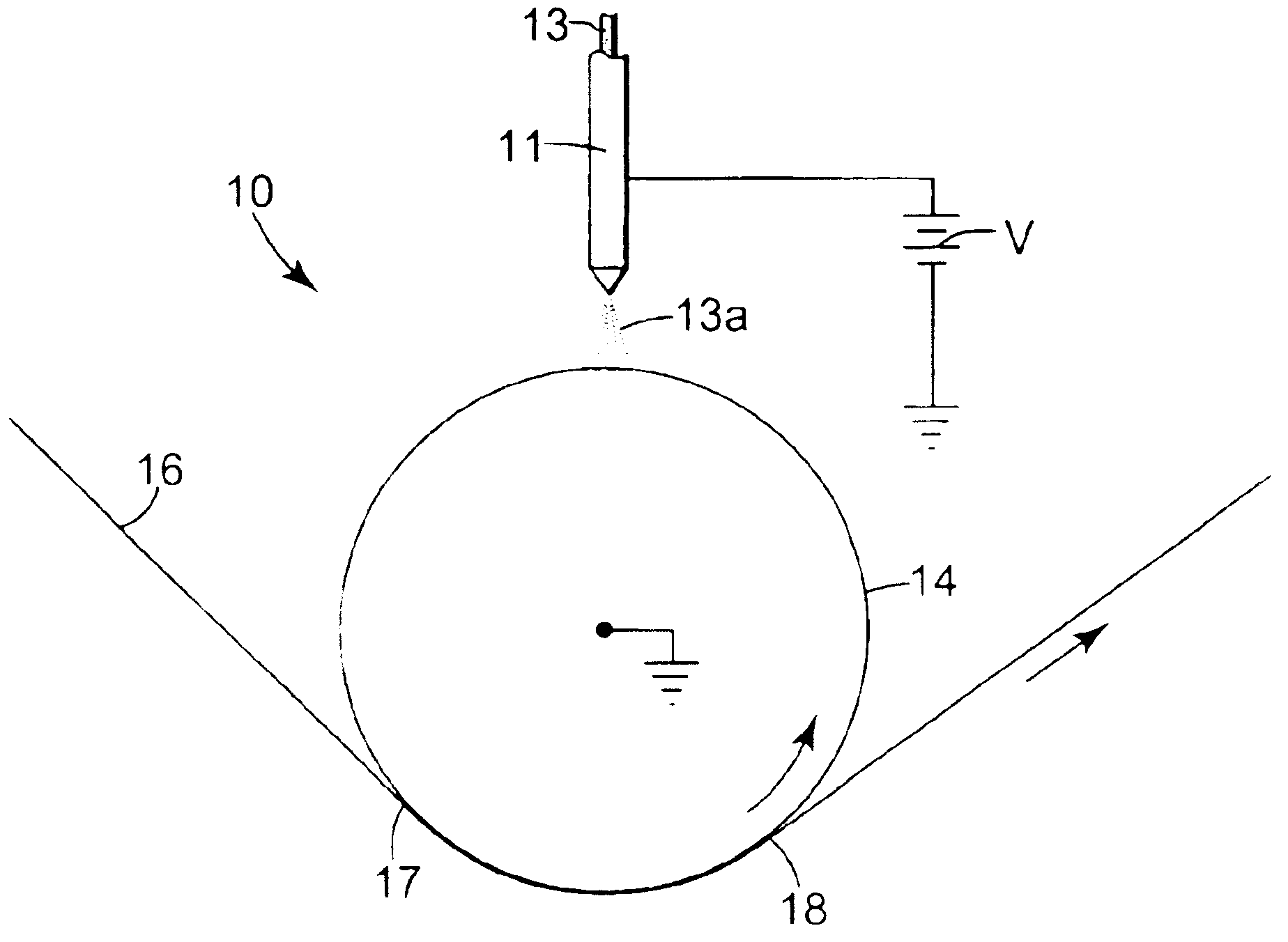
[0100]A 35 micrometer thick, biaxially oriented polypropylene (BOPP) web that had been flame treated on its upper side (Douglas-Hanson Company) was passed over two 7.62 cm diameter idler rolls. The idler rolls had been separated in the machine direction by a sufficient distance to allow a 50.8 cm diameter by 61 cm wide grounded stainless steel drum to be dropped in place between the idler rolls. This caused the web to contact approximately one-half the circumference of the drum and forced the drum to co-rotate at the 15.2 m / min surface speed of the moving web. A solventless silicone acrylate UV curable release formulation like that of Example 10 of U.S. Pat. No. 5,858,545 was prepared and modified by the addition of 0.3 parts per hundred (pph) of 2,2′-(2,5-Thiophenediyl)bis[5-tert-butylbenzoxazole] (UVITEX™-OB fluorescing dye, Ciba Specialty Chemicals Corp.)

[0101]An electrostatic spray head that could operate in the electrospray mode like that of U.S. Pat. No. 5,326,598 was modified...

example 2

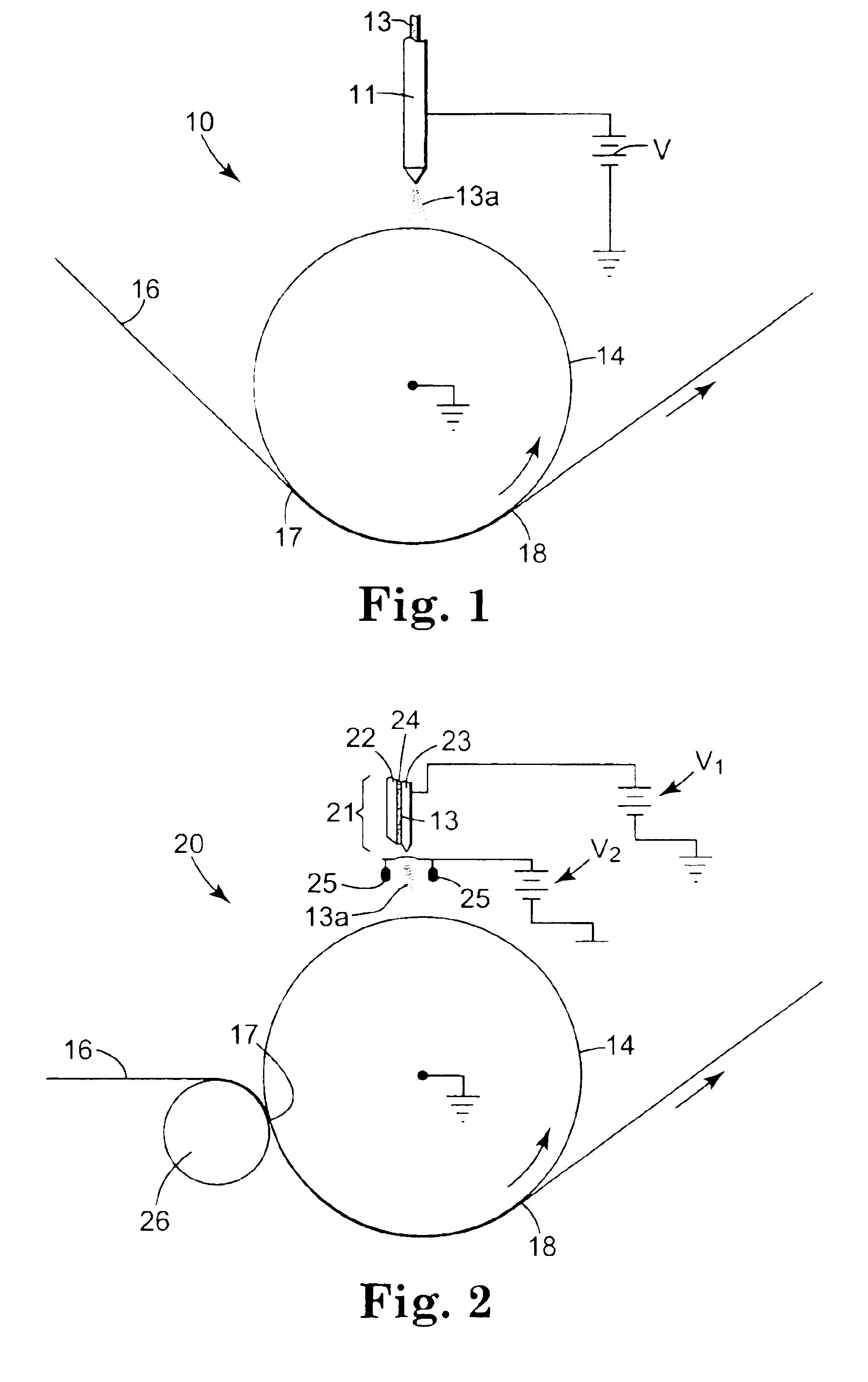
[0103]The apparatus of Example 1 was modified by installing a nip roll that pressed against the underside of the drum at the initial coating line where the liquid first contacted the web. Except for two locations where small gouges (indentations) were present on the nip roll, use of the nip roll eliminated all uncoated areas on the web, and provided a coating having visually improved uniformity. The improved uniformity could be verified by shining a Model 801 “black light” fluorescent fixture (Visual Effects, Inc.) on the wet coating. The UVITEX™ OB fluorescing dye in the release coating radiates blue light under such illumination, and provided a readily discernable illustration of the amount and uniformity of the thin coating deposited the web.

example 3

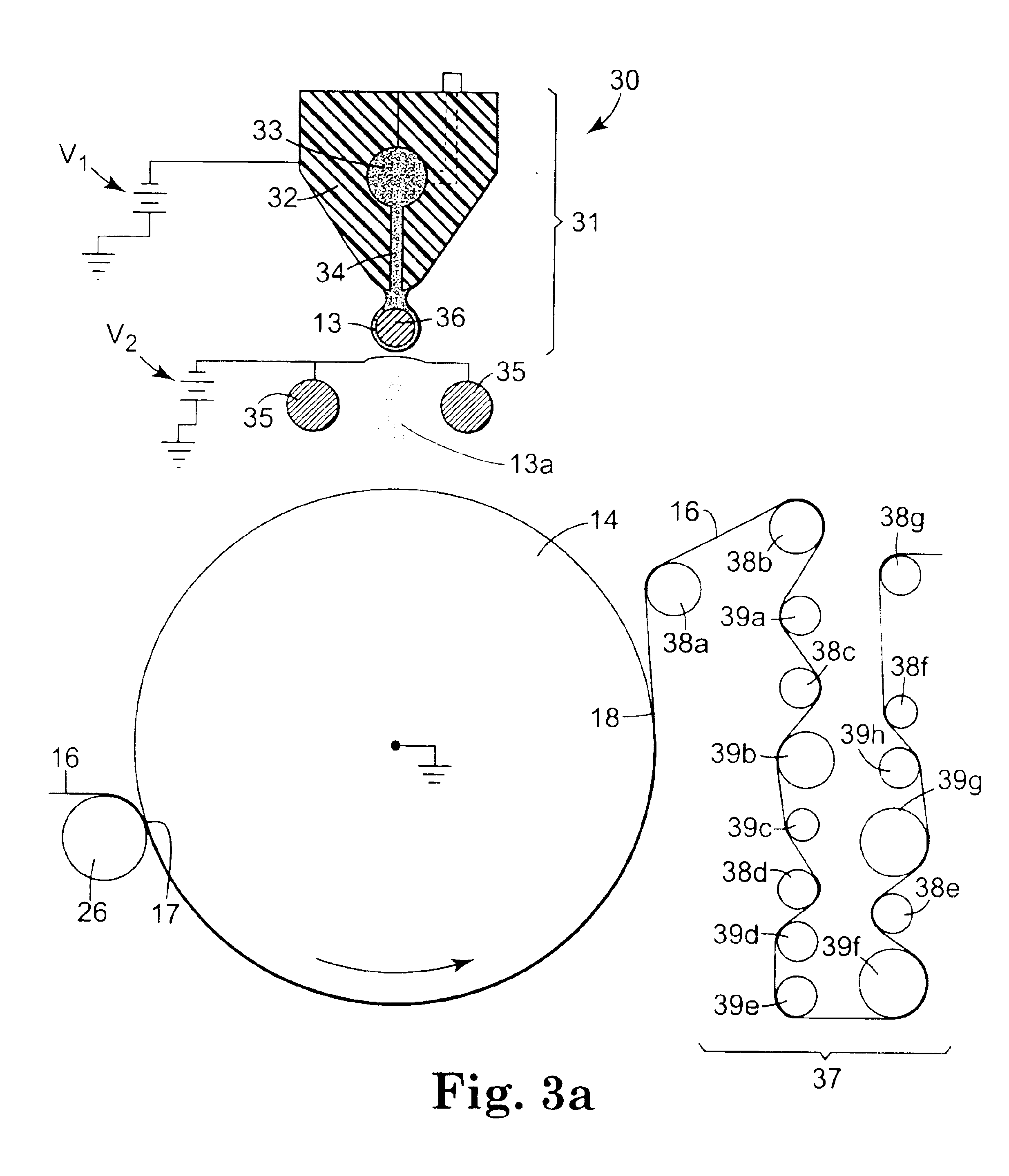
[0104]The apparatus of Example 1 was modified by adding an eight roll improvement station after the second idler roll, and routing the coated web through the improvement station so that the wet side of the web contacted the eight pick-and-place rolls as shown in FIG. 3a. The eight rolls had respective diameters of 54.86, 69.52, 39.65, 56.90, 41.66, 72.85, 66.04, and 52.53 mm, all with a tolerance of plus or minus 0.025 mm. The rolls were obtained from Webex Inc. as dynamically balanced steel live shaft rolls with chrome plated roll faces finished to 16 Ra. The improvement station eliminated all uncoated areas on the web, including the gouge marks caused by the indentations on the nip roll, and provided a coating having further visually improved uniformity when evaluated using black light illumination.


PUM


Abstract

A liquid coating is formed on a substrate by electrostatically spraying drops of the liquid onto a liquid-wetted conductive transfer surface and transferring a portion of the thus-applied liquid from the transfer surface to the substrate. Optionally, one or more nip rolls force the substrate against the transfer surface, thereby decreasing the time required for the drops to spread and coalesce into the coating. Preferably, the coating is passed through an improvement station comprising two or more pick-and-place devices that improve the uniformity of the coating. The coating can be transferred from the conductive transfer surface to a second transfer surface and thence to the substrate. Insulative substrates such as plastic films can be coated without requiring substrate pre-charging or post-coating neutralization. Porous substrates such as woven and nonwoven webs can be coated without substantial penetration of the coating into or through the substrate pores.

Description

CROSS REFERENCE TO RELATED APPLICATION[0001]This application is a divisional of U.S. Ser. No. 09 / 841,380, filed Apr. 24, 2001, now abandoned, the disclosure of which is herein incorporated by reference.TECHNICAL FIELD[0002]This invention relates to devices and methods for coating substrates.BACKGROUND[0003]Electrostatic spray coating typically involves atomizing a liquid and depositing the atomized drops in an electrostatic field. The average drop diameter and drop size distribution can vary widely depending on the specific spray coating head. Other factors such as the electrical conductivity, surface tension and viscosity of the liquid also play an important part in determining the drop diameter and drop size distribution. Representative electrostatic spray coating heads and devices are shown in, e.g., U.S. Pat. Nos. 2,685,536; 2,695,002; 2,733,171; 2,809,128; 2,893,894; 3,486,483; 4,748,043; 4,749,125; 4,788,016; 4,830,872; 4,846,407; 4,854,506; 4,990,359; 5,049,404; 5,326,598; 5,...

Claims


Application Information

Patent Timeline
IPC IPC(8): B05D1/28B05B5/08B05B13/02B05C5/02B05C11/02B05D1/04
CPCB05B13/0228B05C5/0208B05C11/025B05D1/04
Inventor SEAVER, ALBERT E.LEONARD, WILLIAM K.
Owner 3M INNOVATIVE PROPERTIES CO
Why Eureka
Try Eureka