
Imaging optical system including a telescope and an uncooled warm-stop structure

a warm-stop structure and optical system technology, applied in the field of imaging optical systems, can solve the problems of affecting the viewed image as noise, requiring heavy supporting structure, difficult and expensive manufacturing, alignment, testing, etc., and achieve the effect of avoiding adverse effects of warm structure and facilitating rapid cooling

Active Publication Date: 2005-11-29
RAYTHEON CO
View PDF11 Cites 22 Cited by
  • Summary
  • Abstract
  • Description
  • Claims
  • Application Information

AI Technical Summary

Benefits of technology

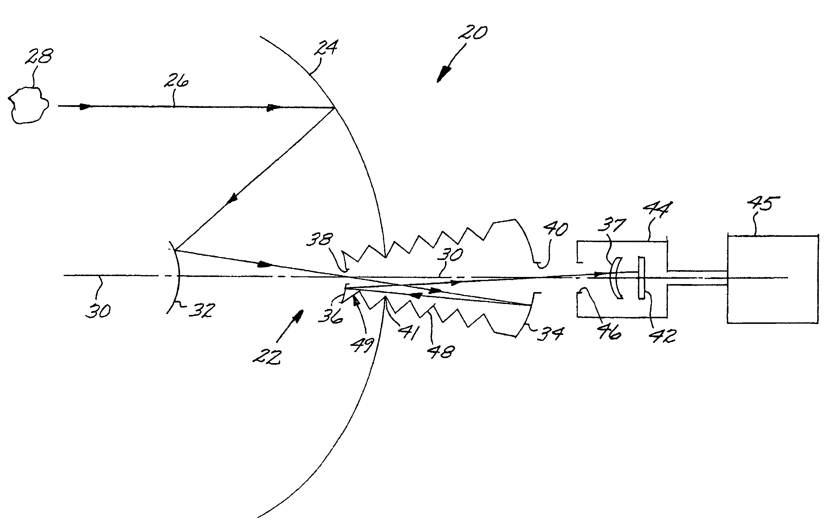
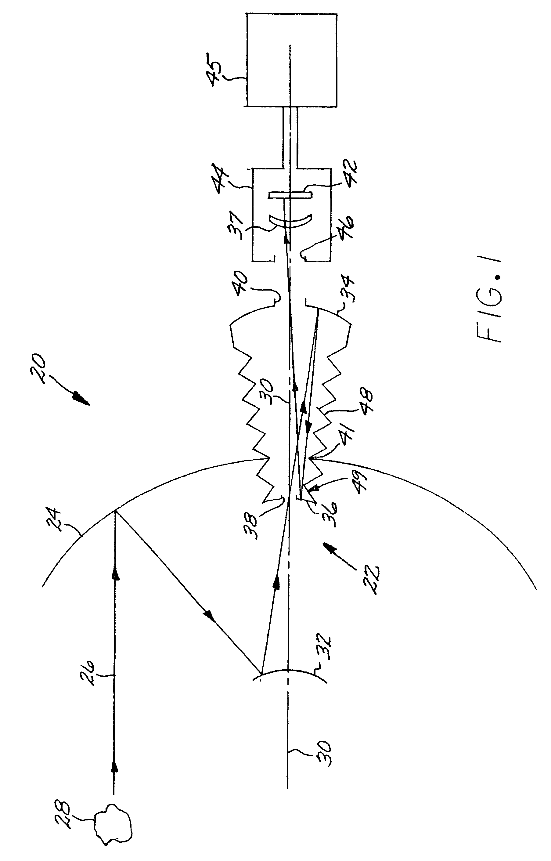
[0006]The present approach provides an imaging optical system that is particularly useful for an infrared sensor system wherein the infrared detector must be rapidly cooled from room temperature to cryogenic temperature prior to commencing operation. The amount of the imaging optical system that must be cooled is held at a minimum, facilitating the rapid cooldown, while avoiding adverse effects of warm structure in the field of view of the infrared detector. The axially symmetric optics subsystem is not cooled, except for one small cooled lens. The size and mass of the imaging optical system are thereby held to a small size.
[0012]The axisymmetric optical design of the optical system greatly facilitates the assembly and testing of the optical system. The large parabolic primary mirror and the primary-secondary mirror combination may be readily tested during fabrication and assembly using null testing, facilitating the manufacturing process. The present approach provides an infrared imaging optical system that has a minimal cooled volume. Specifically, only the infrared detector and the field lens must be cooled by its cooling housing, and the other elements, including both the reflective optical elements and the uncooled warm-stop structure, are outside of the volume of the cooling housing. Other features and advantages of the present invention will be apparent from the following more detailed description of the preferred embodiment, taken in conjunction with the accompanying drawings, which illustrate, by way of example, the principles of the invention. The scope of the invention is not, however, limited to this preferred embodiment.

Problems solved by technology

However, the viewed portion that is not cooled, such as the support structure of the optics subsystem, affects the viewed image as a form of noise.
In this case, the optical elements, such as lenses and / or mirrors, must be highly powered and non-rotationally symmetric, with the result that they are difficult and expensive to manufacture, align, and test, and also require heavy supporting structure.

Method used


Image

  • Imaging optical system including a telescope and an uncooled warm-stop structure
  • Imaging optical system including a telescope and an uncooled warm-stop structure
  • Imaging optical system including a telescope and an uncooled warm-stop structure

Examples


Embodiment Construction

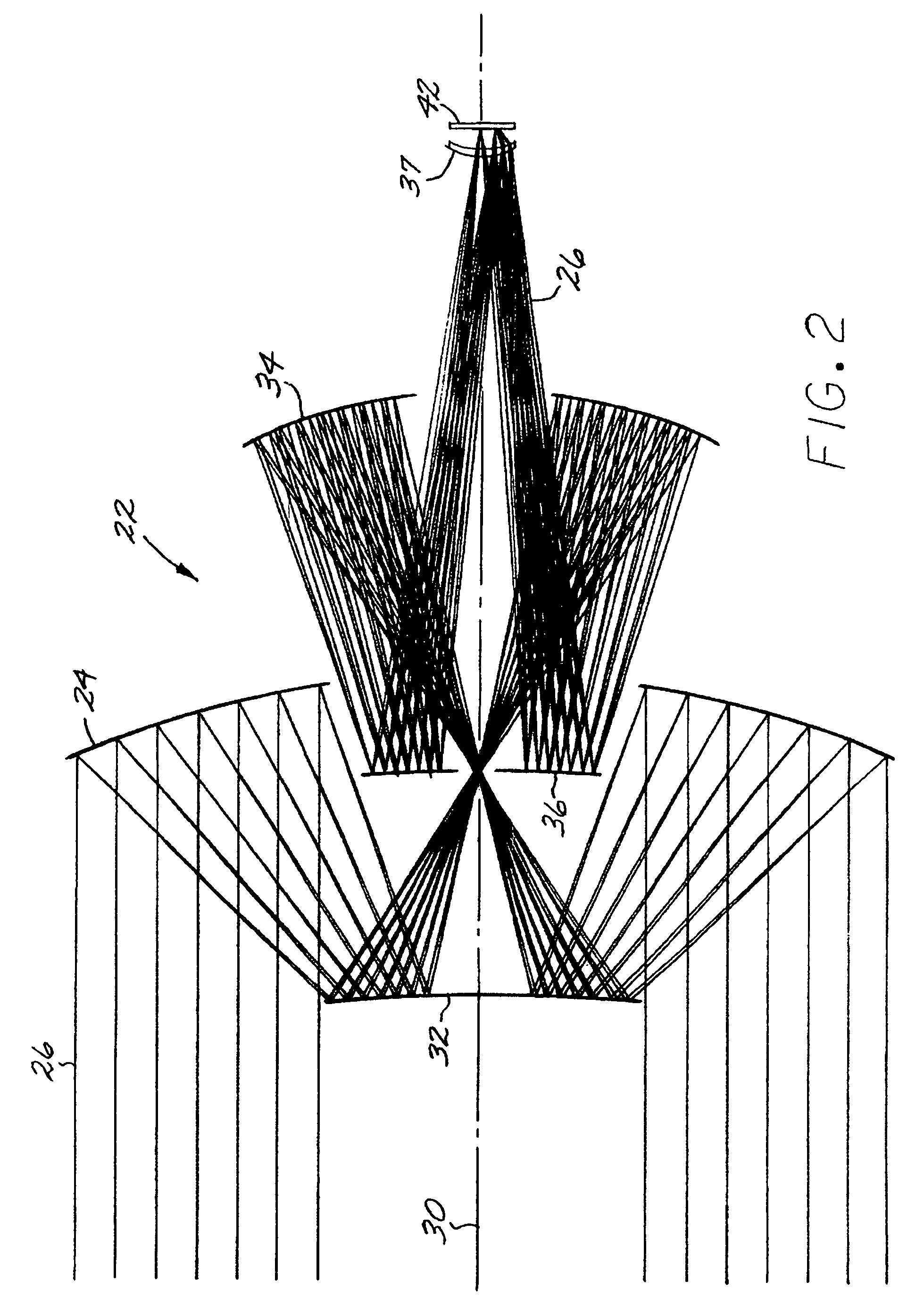
[0017]FIG. 1 depicts an imaging optical system 20 that includes a telescope 22, and FIG. 2 is a ray-path drawing of the telescope 22. The telescope 22 has a positive-optical-power primary mirror 24 that receives a light beam 26 from an external source 28 parallel to a beam axis 30. The light beam 26 may be of any operable wavelength, but is preferably an infrared light beam. A negative-optical-power secondary mirror 32 receives the light beam 26 reflected from the primary mirror 24. A positive-optical-power tertiary mirror 34 receives the light beam 26 reflected from the secondary mirror 32. A negative-optical-power quaternary mirror 36 receives the light beam 26 reflected from the tertiary mirror 34. The light beam 26 reflected from the quaternary mirror 36 passes through a positive-optical-power field lens 37. Preferably, the sum of the optical powers of the primary mirror 24, the secondary mirror 32, the tertiary mirror 34, the quaternary mirror 36, and the field lens 37 is subst...


PUM


Abstract

An all-reflective telescope has, in order, a positive-optical-power primary mirror, a negative-optical-power secondary mirror, a positive-optical-power tertiary mirror, a negative-optical-power quaternary mirror, and a positive-optical-power field lens. The mirrors and lens are axisymmetric about a beam axis. The light beam is incident upon an infrared detector after reflecting from the quaternary mirror. A cooling housing encloses the detector and the field lens, but does not enclose any of the mirrors. An uncooled warm-stop structure outside of the cooling housing but in a field of view of the detector is formed as a plurality of facets with reflective surfaces oriented to reflect a view of an interior of the cooling housing back to the interior of the cooling housing.

Description

[0001]This invention relates to imaging optical systems and, more particularly, to a telescope optimized for use with an infrared detector.BACKGROUND OF THE INVENTION[0002]In one type of imaging optical system using a sensor, an infrared detector is placed into a cooling housing. The cooling housing maintains the detector at the required cryogenic temperature for efficient operation of the detector. The housing has an aperture therethrough so that the infrared detector may view an external scene through the aperture. In most cases, there is an optics subsystem that images the external scene onto the detector. The optics subsystem may be a telescope that alters the magnification of the scene when it is imaged onto the detector. For many applications, the optics subsystem must be as compact as possible, while remaining consist with the required optical performance.[0003]In addition to the scene, some of the structure of the imaging optical system is within the field of view of the det...

Claims


Application Information

Patent Timeline
Patent Type & Authority Patents(United States)
IPC IPC(8): G01J5/06G02B5/10G02B17/00G02B27/00H01J3/14
CPCG01J5/06G02B17/084G02B17/0852G02B27/0018
Inventor THERIAULT, P. CHRISRADAU, JR., RUDOLPH E.
Owner RAYTHEON CO
Learn More