Method for guiding a medical instrument through a body

a technology of medical instruments and body, applied in the field of medical instruments, can solve the problems of inaccurate images, cardiac problems, and inability to provide images of the arterial wall or plaque positioned immediately forward of the catheter, and achieve the effects of convenient automatic control and advancement of the catheter through the body, convenient implementation, and convenient operation

Inactive Publication Date: 2005-11-29
SPECTRANETICS
View PDF7 Cites 126 Cited by
  • Summary
  • Abstract
  • Description
  • Claims
  • Application Information

AI Technical Summary

Benefits of technology

[0019]The above described guidance systems facilitate obtaining more accurate images than obtained using ultrasound. In addition, such systems are believed to be substantially easy to im

Problems solved by technology

Such plaque build-up restricts circulation and often causes cardiovascular problems, especially when the build-up occurs in coronary arteries.
Utilizing known ultrasound sensors as described above results in displaying images of the portions of the arterial wall which are radially disposed about the catheter, but does not provide images of the arterial wall or plaque positioned immediately forward the catheter.
Sound waves that are

Method used


Image

  • Method for guiding a medical instrument through a body
  • Method for guiding a medical instrument through a body
  • Method for guiding a medical instrument through a body

Examples


Embodiment Construction

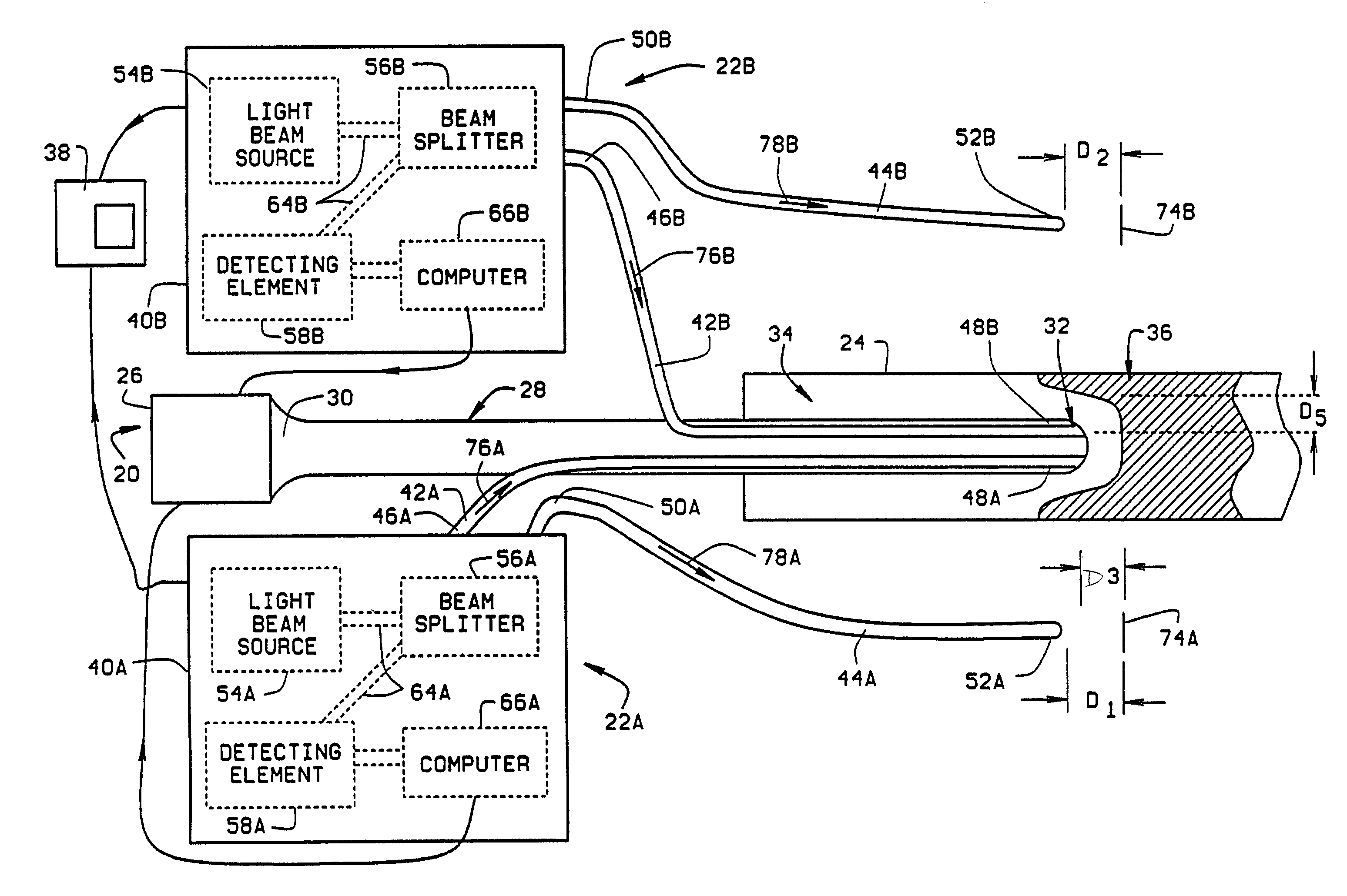
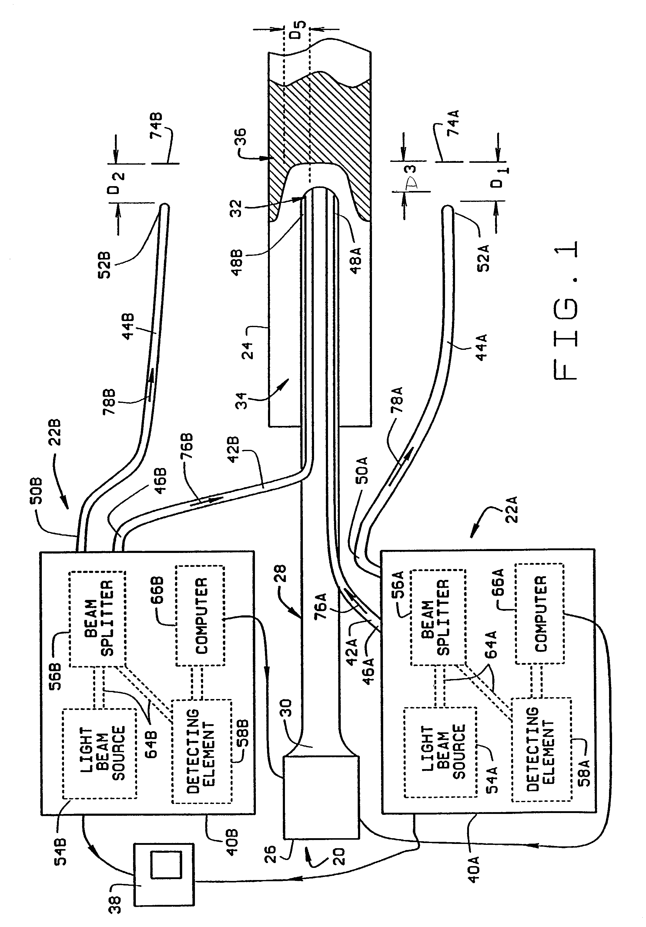
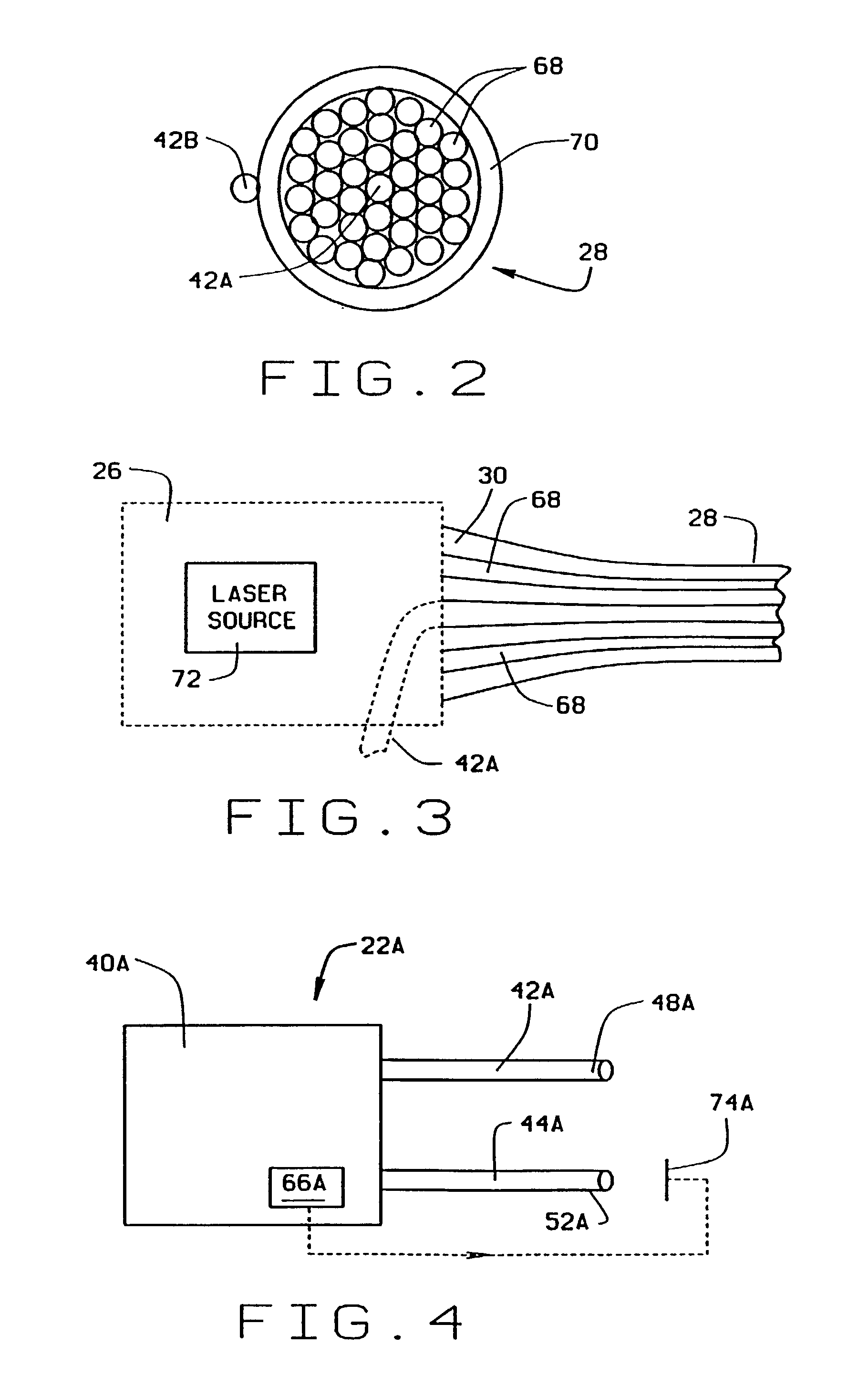
[0024]FIG. 1 is a pictorial illustration of a catheter assembly 20 including two guidance systems 22A and 22B in accordance with one embodiment of the present invention inserted into a blood vessel 24 of a body. Catheter assembly 20 includes a control element 26 and a catheter body 28. Catheter body 28 has a first end 30 and a rounded, or hemispherical, second end, or head, 32, and includes a plurality of optic fibers (not shown in FIG. 1). Catheter body first end 30 is communicatively coupled to control element 26 and catheter body second end 32 is positioned within an interior 34 of blood vessel 24 adjacent tissue to be imaged, e.g., plaque 36.

[0025]Each guidance system 22A and 22B includes a respective control element 40A and 40B, a respective first, or measuring, optic fiber 42A and 42B, and a respective second, or reference, optic fiber 44A and 44B. First optic fibers 42A and 42B include respective first ends 46A and 46B and respective second ends 48A and 48B, and are coupled t...


PUM


Abstract

Guidance systems for guiding a catheter through tissue within a body are described. In one form, the system is implemented in connection with a catheter which includes a catheter body having a optic fibers extending between a first end and a second end thereof. The guidance system is coupled to the catheter body and includes a first optic fiber, a second optic fiber, and a detecting element. The first optic fiber includes a first end and a second end, and is coupled to the catheter body so that the first optic fiber second end is adjacent the catheter second end. The second optic fiber also includes a first end and a second end, and a reference mirror is positioned adjacent the second optic fiber second end. The first optic fiber first end is communicatively coupled to the detecting element and the second optic fiber first end is communicatively coupled to the detecting element. The detecting element is configured to determine interference between a light beam propagating through the first optic fiber and a light beam propagating through the second optic fiber.

Description

[0001]This application is a divisional of U.S. application Ser. No. 09 / 276,379, filed Mar. 25, 1999, now U.S. Pat. No. 6,463,313, which is a continuation of U.S. application Ser. No. 08 / 890,631, filed Jul. 9, 1997, now U.S. Pat. No. 6,048,349, both of which are hereby incorporated by reference.FIELD OF THE INVENTION[0002]This invention relates generally to medical instruments and, more particularly, to systems and methods for guiding medical instruments through a body or a portion of the body, such as a blood vessel.BACKGROUND OF THE INVENTION[0003]Disease processes, e.g., tumors, inflammation of lymph nodes, and plaque build-up in arteries, often afflict the human body. To treat such disease, it often is necessary to insert a medical device into the body, and to guide the medical device to the diseased site. Once the medical device is adjacent the diseased site, the medical device typically is used to photoablate or otherwise remove or reduce the diseased tissue.[0004]As one specif...

Claims


Application Information

Patent Timeline
IPC IPC(8): A61B1/04A61B17/00A61B17/22A61B18/22A61B18/24A61B19/00A61M25/01A61M25/095
CPCA61B1/042A61B18/245A61B2017/00057A61B2017/00106A61B2017/22075A61B2018/2211A61B2019/5217A61B2019/5231A61M25/01A61B2090/373A61B2090/3614
Inventor WINSTON, THOMAS R.NEET, JOHN M.
Owner SPECTRANETICS
Why Eureka
Try Eureka