
Iontophoresis device

a technology of iontophoresis and electrodes, applied in electrotherapy, therapy, etc., can solve the problems of high output voltage, inability to confirm the conductor state, and user malais

Inactive Publication Date: 2005-11-29
HISAMITSU PHARM CO INC
View PDF7 Cites 90 Cited by
  • Summary
  • Abstract
  • Description
  • Claims
  • Application Information

AI Technical Summary

Benefits of technology

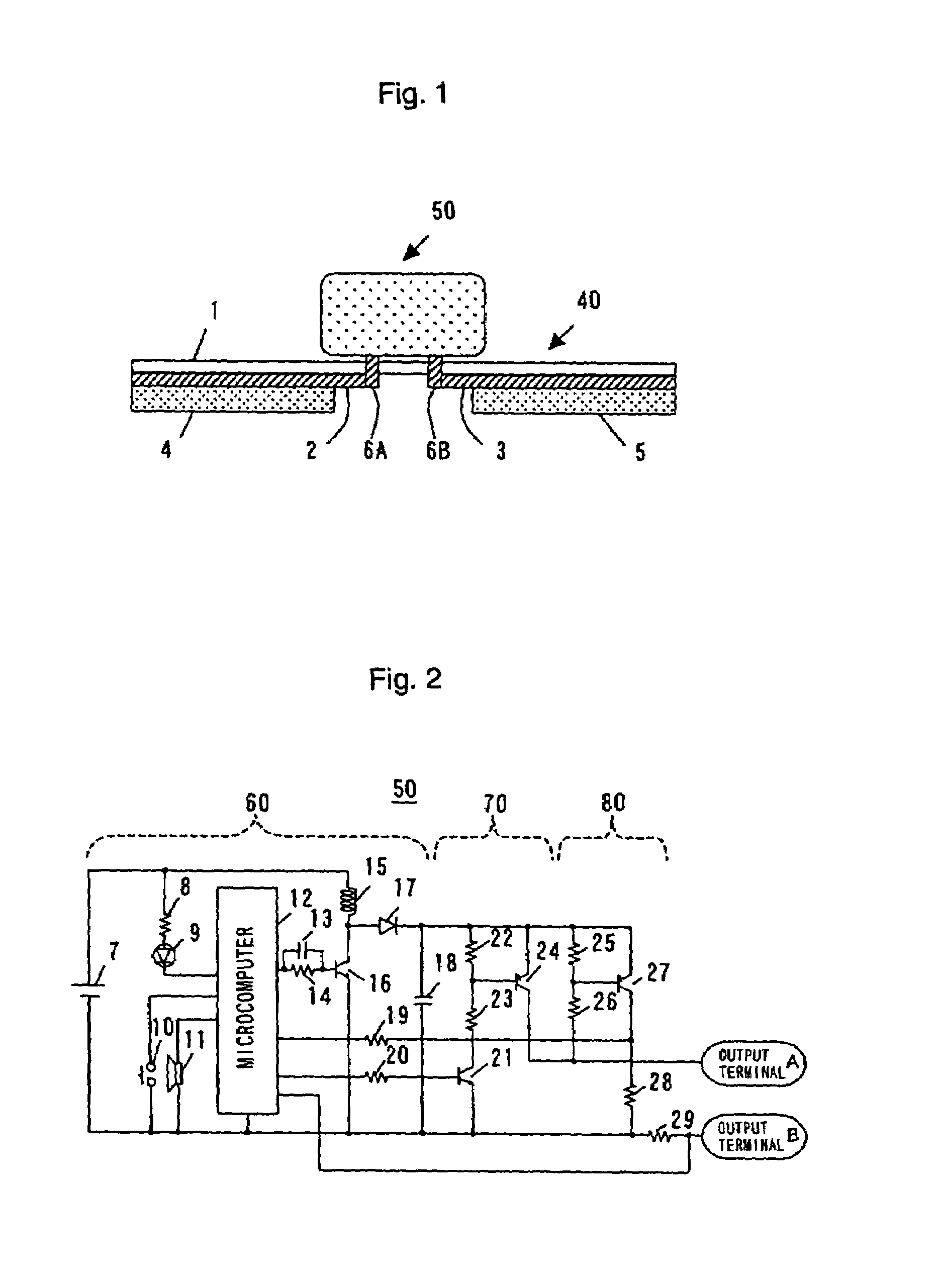
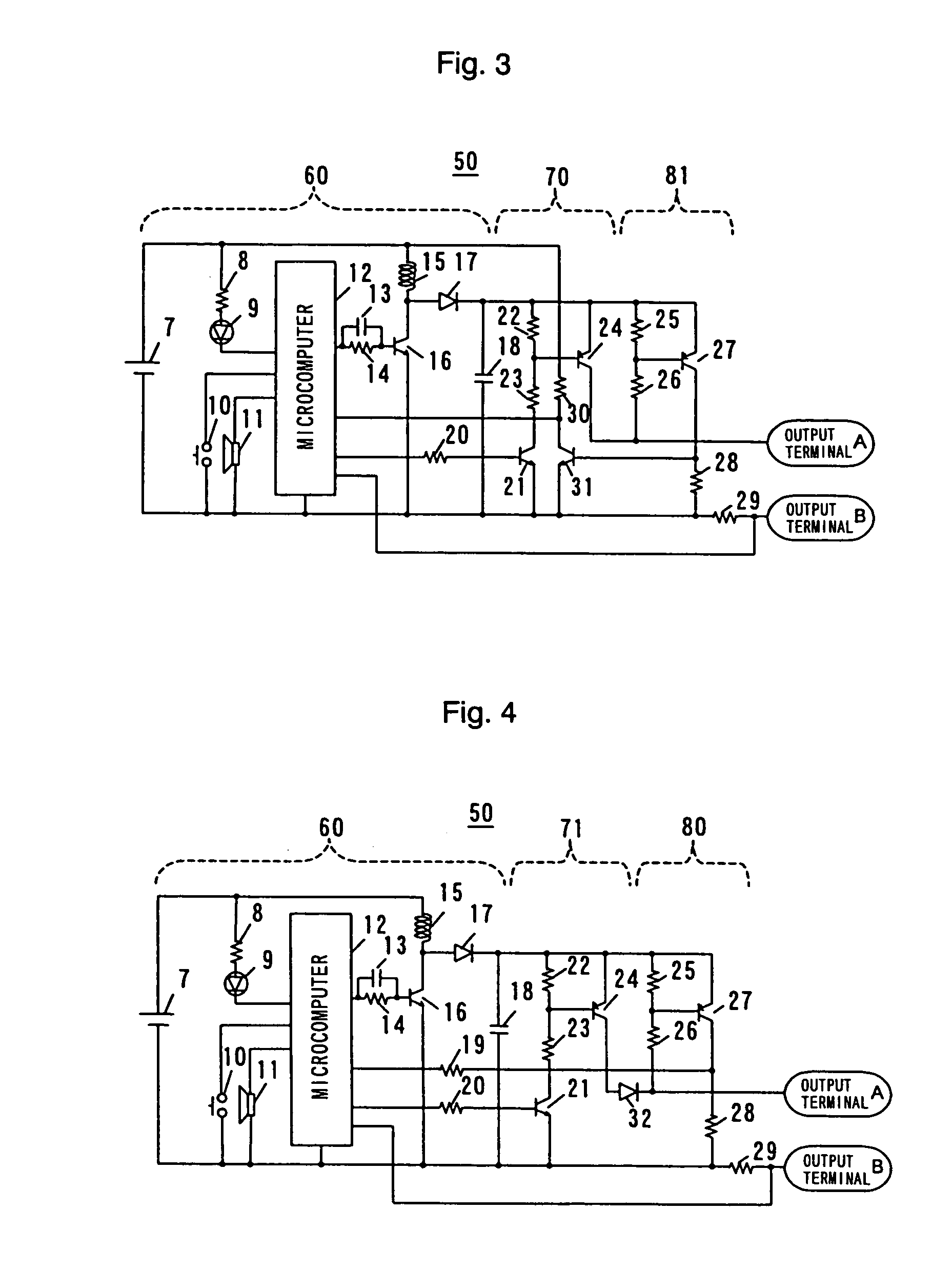
[0007]The inventors have examined the conventional techniques to solve the above described problems. And, as a result, the present invention has been achieved by finding the fact that an abnormal conductivity detecting means is provided for detecting whether or not supply of electric energy is normal, and then abnormal conductivity can be effectively detected at the beginning of energization and during energization, by performing the detecting action of the abnormal conductivity detecting means that is carried out at the time of the non-output action of the device. In other words, according to the present invention, at the beginning of energization, the abnormal conductivity detecting means detects whether or not the supply of electric energy is normal with reference to a preset high impedance. When the result is determined as normal, the device starts an output action of the electric energy at a low impedance preset for medication. When the result is determined as abnormal, the device does not start the output action of the electric energy. On the other hand, during energization, the output action by the electric energy and the detecting action by the abnormal conductivity detecting means are alternated, so that the output action of the electric energy stops when the supply of electric energy is determined as abnormal by the abnormal conductivity detecting means.

Problems solved by technology

In case of the above described method that makes the monitoring by applying a comparatively high voltage to the object spot at the beginning of energization, however, a problem arises; concretely, the high output voltage makes the user feel malaise.
In addition, the above described method which begins monitoring of both current and voltage of the power-driven transportation after the impedance on the object spot skin is stabilized is to be confronted with another problem that the current conducting state cannot be confirmed until the impedance on the object spot skin is stabilized.

Method used


Image

  • Iontophoresis device
  • Iontophoresis device
  • Iontophoresis device

Examples


Embodiment Construction

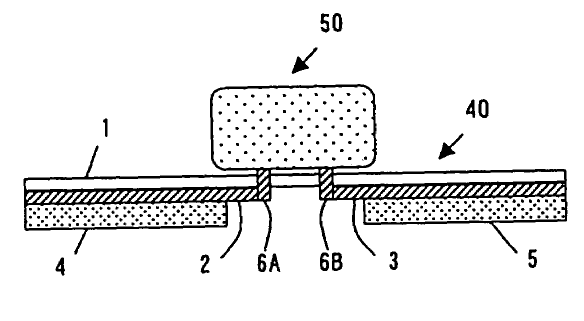
[0015]FIG. 1 is a conceptual cross-sectional view of the iontophoresis device of the present invention. This device, as shown in FIG. 1, comprises a preparation 40 for iontophoresis holding a medicine and a device 50 for iontophoresis that functions as a power source that generates electric energy required for this preparation to supply the medicine to the object skin or mucosa.

[0016]The iontophoresis preparation 40 is composed of an insulating substrate 1, a pair of electrodes 2 and 3 disposed on the insulating substrate 1 with a space therebetween, a medicine pool 4 disposed in contact with the electrode 2, an electrolyte pool 5 disposed in contact with the electrode 3, and tabs 6A and 6B used to attach the device 50 to the preparation 40. The tabs 6A and 6B are connected to the electrodes 2 and 3 respectively. When the iontophoresis preparation is provided with two or more medicine pools, the electrolyte pool is replaced with one of the medicine pools. The medicine and electrolyt...


PUM


Abstract

This is an iontophoresis device preferred to detect abnormal conductivity at the beginning of energization and during energization. The iontophoresis device has a device (50) as a power source and the device (50) comprises an electric energy generating portion (60) generating electric energy, an output portion (70) outputting the electric energy, and an abnormal conductivity detecting portion (80) detecting whether or not the electric energy is supplied normally. The detecting action of the abnormal conductivity detecting portion (80) is carried out at the time of the non-output action of the output portion (70). During the energization, the output action by the output portion (70) and the detecting action by the abnormal conductivity detecting portion (80) are alternated in response to a command received from the microcomputer (12).

Description

TECHNICAL FIELD[0001]The present invention relates to an iontophoresis device applied to transdermal or transmucosal administration, more particularly, having a function for detecting abnormal conductivity.BACKGROUND ART[0002]The iontophoresis is a system used for quickening skin absorption with electricity. The object of the iontophoresis is to quicken permeation of medicine molecules through the skin barrier with good use of a force that moves positively charged molecules from positive pole to negative pole and negatively charged molecules from negative pole to positive pole in an electric field generated mainly due to current conducting. [Refer to (Journal of Controlled Release) pp. 213 to 220, Vol. 18, 1992; Advanced Drug Delivery Review) p. 119, Vol. 9, 1992; Pharmaceutical Research) pp. 318 to 326, Vol. 3, 1986.][0003]Such an iontophoresis device having been known well is provided with means for checking whether or not the movement of molecules (including drugs) is done normal...

Claims


Application Information

Patent Timeline
IPC IPC(8): A61N1/30
CPCA61N1/30
Inventor INOUE, KAZUTAKA
Owner HISAMITSU PHARM CO INC
Learn More