System of distributed microprocessor interfaces toward macro-cell based designs implemented as ASIC or FPGA bread boarding and relative common bus protocol

a distributed microprocessor and interface technology, applied in the field of microprocessor interfacing, can solve the problems of developing fully verified complex designs, developing very complex design implementations, and further bus based interconnection resources, and achieves the effects of easy development and interfacing of user macro-cells, high modularity, and rapid prototyping

Inactive Publication Date: 2005-11-29
ITALTEL SPA
View PDF5 Cites 61 Cited by
  • Summary
  • Abstract
  • Description
  • Claims
  • Application Information

AI Technical Summary

Benefits of technology

[0088]To achieve said purposes the subject of the present invention is an interface between a microprocessor, or local bus, and user developed macro-cells having the modular and distributed architecture described in claim 1.
[0089]Main module and peripherals modules of the distributed interface of the present invention may be advantageously implemented like further macro-cells.
[0090]The distributed interface of the present invention has a great impact on the new user developed macro-cells. Having in fact removed from the corresponding user developed macro-cell of the prior art the majority of hardware primitives only devoted to interfacing the configuration and control microprocessor, a new simpler macro-cell basic architecture results which not needs the “ad hoc” interfaces design or redesign of the prior art. The transfer of all those above mentioned resources into configurable peripheral modules of the microprocessor distributed interface allows a great uniform design of all genders of macro-cells, indifferently belonging to the user or the interface itself. The development and interfacing of user macro-cells is made easier consequently and the designer can concentrate prevalently on the macro-cell function.
[0091]Another advantage of the distributed interface of the invention, due to its high modularity, consists in furnishing a scalable architecture. It is in fact convenient to pro...

Problems solved by technology

Nowadays the huge grown in performances and density of gates in modern gate arrays has made possible very complex design implementations.
The resulting challenge is to develop fully verified complex designs granting at the same time a short time to market.
In very complex cases further bus based interconnection resources are present.
Due to the microprocessor independence, local buses are generally more complex than back-plane buses in terms of protocol and more sophisticated in terms of features.
Moreover microprocessor, in general, are not optimized for burst transfers except for the DMA (Direct Memory Access) mode.
“Classic” architectures very often are not compliant to this requirement of portability between ASIC implementation and an FPGA bread boarding implementation.
Until now drawbacks of the known interfacing architectures have ...

Method used


Image

  • System of distributed microprocessor interfaces toward macro-cell based designs implemented as ASIC or FPGA bread boarding and relative common bus protocol
  • System of distributed microprocessor interfaces toward macro-cell based designs implemented as ASIC or FPGA bread boarding and relative common bus protocol
  • System of distributed microprocessor interfaces toward macro-cell based designs implemented as ASIC or FPGA bread boarding and relative common bus protocol

Examples


second embodiment

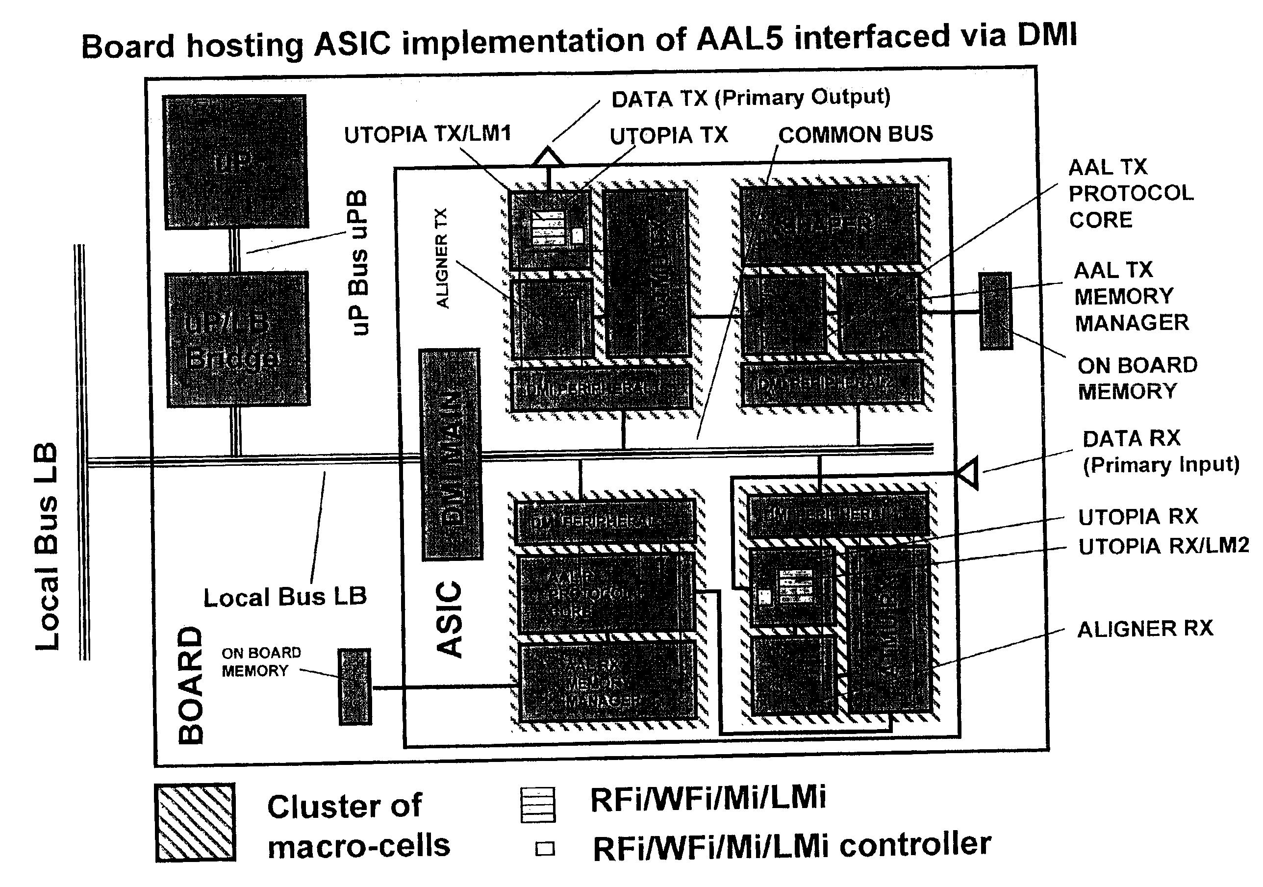
[0162]With reference to FIG. 10 the invention is shown. It differs from the embodiment of FIG. 9 mainly for the absence of the block uP / LB BRIDGE at a left side of the BOARD and for the presence of an additional block DMI MAIN2 at the opposite side of the board. In FIG. 10 the microprocessor uP is directly connected to the block DMI MAIN1 inside the ASIC by means of the microprocessor bus uPB. Block DMI MAIN2 has a first side connected to a local bus LB on the back-plane, and the opposite side connected to a bus COMMON-BUS 2, while the block DMI MAIN1 is interposed between uPB and COMMON-BUS 1 buses, the last bus is the COMMON-BUS of the previous FIG. 9. First and third clusters of macro-cells are unchanged, while the remaining two clusters each includes an additional DMI PERIPHERAL macro-cell, both connected to the COMMON-BUS 2. More precisely, the second cluster includes a DMI PERIPHERAL6 macro-cell connected to AAL TX MEMORY MANAGER and AAL TX PROTOCOL CORE macro-cells instead of...

third embodiment

[0163]With reference to FIG. 11 the invention is shown which differs from the embodiment of FIG. 9 only for the particular implementation in which the four clusters of macro-cells and the block DMI MAIN constituting the ASIC of FIG. 9 are implemented as many FPGA. The presence of the COMMON-BUS highly reduces the number of interconnections between DMI PERIPHERALs and relative user developed macro-cells; this makes the new implementation suitable for prototyping the ASIC, being the architecture the same for both ASIC and FPGA bread-boarding, no changes are necessary changing the implementation technology.

[0164]With reference to FIG. 12 the COMMON-BUS of the previous FIGS. 9 to 11 is detailed into functionally structured sub buses. This means that some buses could not be physically present in the implementation but their function must be implemented (e.g. some bus can be multiplexed in time sharing fashion on the same physical support). Each sub bus has either direction upstream or do...


PUM


Abstract

A distributed interface between a microprocessor or a standard bus and user macro-cells belonging to an ASIC, or FPGA, or similar silicon devices includes a main module connected to the microprocessor bus on one side and to a COMMON-BUS inside the interface on which a cluster of peripheral modules is appended on the other side. Peripheral modules are also connected to the user macro-cells through as multiple point-to-point buses to transfer signals two directions. A set of hardware and firmware resources such as registers, counters, synchronizers, dual port memories (e.g. RAM, FIFO) either synchronous or asynchronous with respect to macro-cells clock is encompassed in each peripheral module. Subsets of the standard resources are diversely configured in each peripheral module in accordance with specific needs of the user macro-cells.

Description

FIELD OF THE INVENTION[0001]The present invention is referred to the field of the microprocessor interfacing and more precisely to a system of distributed microprocessor interfaces toward macro-cells based designs implemented as ASIC or FPGA bread boarding and relative COMMON-BUS protocol.BACKGROUND OF THE INVENTION[0002]Nowadays the huge grown in performances and density of gates in modern gate arrays has made possible very complex design implementations. The resulting challenge is to develop fully verified complex designs granting at the same time a short time to market. The nowadays tendency is to manage complexity by exploiting CAD (Computer Aided Design) tools made available on the market to the designer for promoting large net-list integration directly on a silicon die, i.e. Field Programmable Gate Arrays (FPGA), or Application Specific Integrated Circuit (ASIC). A parallel way to dominate the increasing complexity of designs and to allow an easier verification is the nowadays...

Claims


Application Information

Patent Timeline
IPC IPC(8): G06F1/24G06F13/14G06F13/38G06F13/40G06F17/50
CPCG06F17/5045G06F30/30
Inventor GEMELLI, RICCARDOPAVESI, MARCODE BLASIO, GIUSEPPE
Owner ITALTEL SPA
Why Eureka
Try Eureka