Water heater

a water heater and water tank technology, applied in the field of water heaters, can solve the problems of difficult to achieve high heat exchange efficiency, insufficient recovery of sensible heat, and high cost, and achieve the effect of efficient operation

Inactive Publication Date: 2005-12-06
PALOMA IND LTD
View PDF8 Cites 16 Cited by
  • Summary
  • Abstract
  • Description
  • Claims
  • Application Information

AI Technical Summary

Benefits of technology

[0023]In the water heater according to the first aspect having the above configuration, hot exhaust gas passing through the main heat exchanger directly flows into the secondary heat exchanger and the drain evaporator respectively. By utilizing this hot exhaust gas, in the secondary heat exchanger heat recovery is conducted efficiently and in the drain evaporator drain is evaporated efficiently.
[0025]Therefore, in the present invention the drain evaporator evaporates drain efficiently with hot exhaust gas and the secondary heat exchanger efficiently recovers exhaust gas heat by utilization of the hot exhaust gas.

Problems solved by technology

However, in such a water heater, hot exhaust gas is discharged from the heat exchanger even if heat recovery is insufficient for preventing drain generation therein, whereby it is difficult to achieve high heat exchange efficiency.
As a result, sensible heat is not recovered sufficiently.
In order to cope with this problem, in a conventional condensing water heater, a drain neutralization apparatus has been required as recited in Japanese Patent Publication of unexamined application No. 2002-195645, and thus, the cost is fairly expensive.
Moreover, it is necessary to change a neutralizing agent used in the neutralization apparatus for a certain period, which is a heavy burden for a user.
According to this water heater, the same amount of heat as that of latent heat recovered by the secondary heat exchanger is used for drain evaporation, resulting that latent heat is not recovered.
Further, in this case it is unnecessary to provide a drain neutralization apparatus with the water heater, which makes the cost lower.
However, in the prior art, as the secondary heat exchanger and the drain evaporator are provided with a common exhaust gas route, the following problems existed.
Due to this, in the above configuration, it is necessary to limit recovery efficiency of the exhaust gas purposely in order to evaporate received drain completely.
On the other hand, when the drain evaporator provided with the exhaust gas route is located at the upstream of the secondary heat exchanger, heat energy of the exhaust gas is wasted away before it reaches the secondary heat exchanger since the heat energy is utilized when the drain turns into gas in the drain evaporator.

Method used


Image

  • Water heater
  • Water heater
  • Water heater

Examples


Embodiment Construction

[0031]To clarify the above-described configuration and operation of the present invention, the preferred embodiment of the present invention will be explained below.

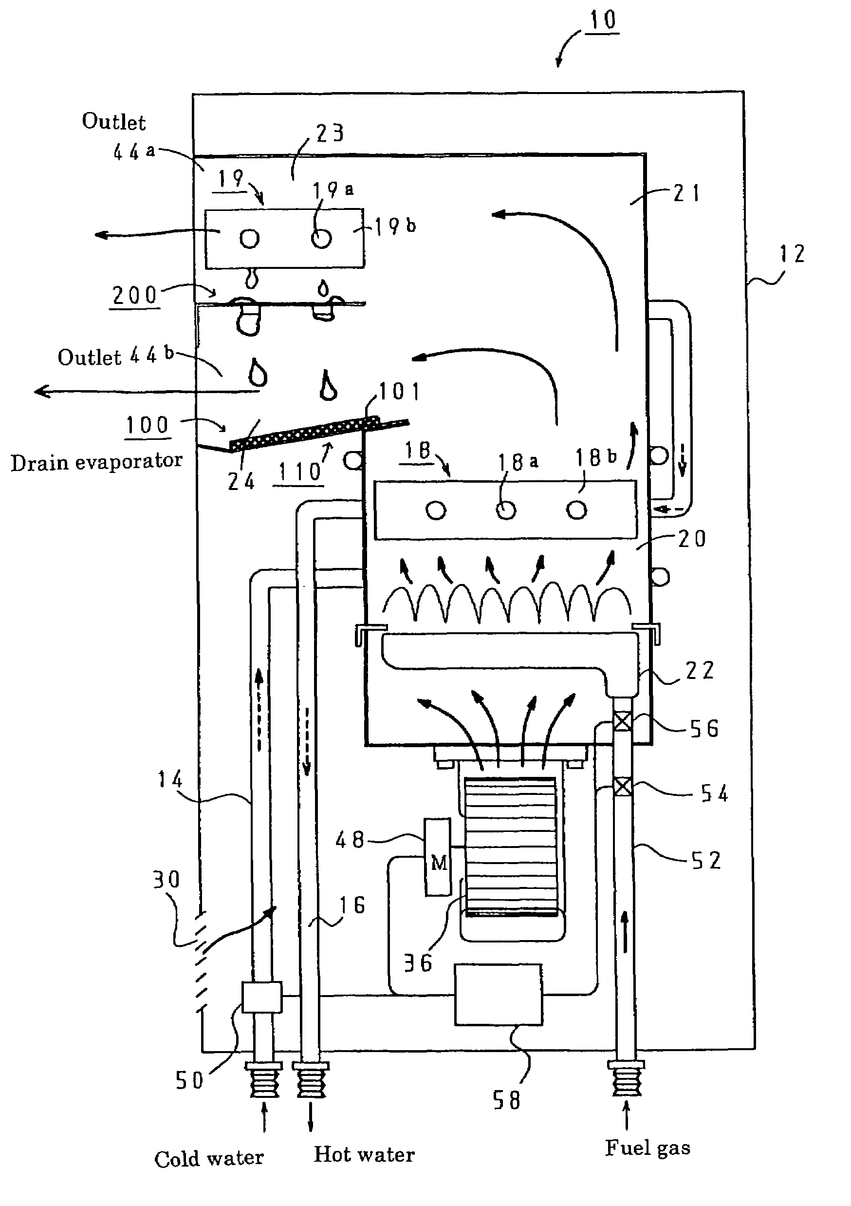
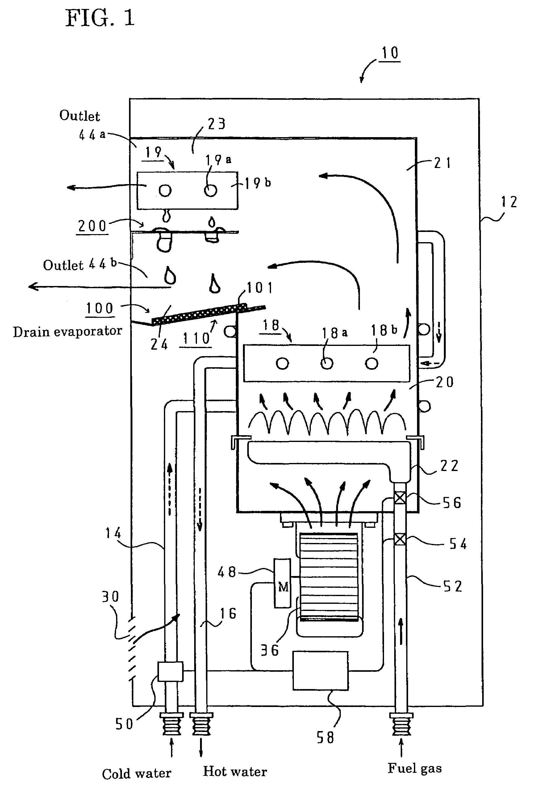
[0032]As shown in FIG. 1, a water heater according to the embodiment of the present invention includes an apparatus casing 12 which has a combustion chamber 20 below which a blower 36 connected with a DC motor 48 is provided. It should be noted that the apparatus casing 12 has an inlet 30 for supplying air for combustion.

[0033]In the combustion chamber 20, provided are, from the downstream side, a burner 22 for burning mixed gas made of fuel gas and primary air from the blower 36, and a main heat exchanger 18 for recovering almost all sensible heat of exhaust gas discharged from the burner 22. Above the main heat exchanger 18, a hot exhaust gas chamber 21 is provided into which still hot exhaust gas passing through the main heat exchanger 18 flows. At the lateral side of the hot exhaust gas chamber 21, a first exhaust ga...


PUM


Abstract

A water heater is provided in which neutralization process of drain is not required and an excellent heat efficiency is achieved. A route of exhaust gas which is passing through the main heat exchanger 18 is divided into a first exhaust gas chamber 23 having a secondary heat exchanger 19 and a second exhaust gas chamber 24 having a drain evaporator. Because of this, hot exhaust gas which is passing through only the main heat exchanger 18 flows into both the secondary heat exchanger 19 and the drain evaporator 100. Therefore, in the secondary heat exchanger 19 exhaust gas heat can be efficiently recovered by utilizing the hot exhaust gas, and in the drain evaporator 100 drain can be evaporated efficiently by utilizing the hot exhaust gas.

Description

BACKGROUND OF THE INVENTION[0001]This application claims the benefit of Japanese Patent Application Numbers 2003-296107 filed on Aug. 20, 2003 and 2003-411181 filed on Dec. 10, 2003, the entirety of which is incorporated by reference.[0002]1. Field of the Invention[0003]The present invention relates to a water heater having a heat exchanger which heats flowing water by combustion exhaust gas.[0004]2. Description of Related Art[0005]Conventionally, a water heater is known, which includes a heat exchanger with which a cold water supply pipe and a hot water outlet are connected, a burner which heats the heat exchanger and a blower which supplies fresh air for combustion to the burner.[0006]In this water heater, the heat exchanger heats flowing water by combustion exhaust heat from the burner, and hot water is discharged from the hot water outlet.[0007]However, in such a water heater, hot exhaust gas is discharged from the heat exchanger even if heat recovery is insufficient for prevent...

Claims


Application Information

Patent Timeline
Patent Type & Authority Patents(United States)
IPC IPC(8): F24H8/00
CPCF24H8/006Y02B30/106Y02B30/00
Inventor KOBAYASHI, TOSHIHIROICHIKAWA, TOMOHIRO
Owner PALOMA IND LTD
Why Eureka
Try Eureka