
Common rail type fuel injection system

a fuel injection system and common rail technology, applied in the direction of liquid fuel feeders, machines/engines, electric control, etc., can solve the problems of pump pressure-feeding quantity of supply pumps that cannot be taken into account by technology, and achieve high injection accuracy and prevent variation in actual injection quantity

Inactive Publication Date: 2005-12-06
DENSO CORP
View PDF9 Cites 18 Cited by
  • Summary
  • Abstract
  • Description
  • Claims
  • Application Information

AI Technical Summary

Benefits of technology

This approach prevents variations in actual injection quantity due to changes in pump discharge rate, enhancing injection accuracy and optimizing fuel delivery based on the operating state of the engine.

Problems solved by technology

However, this technology does not take into account the fact that a pump pressure-feeding quantity of the supply pump changes during the injection period if the injection start timing changes in accordance with a change in the operating state and if the pump discharge rate changes because of the change in the injection start timing.

Method used


Image

  • Common rail type fuel injection system
  • Common rail type fuel injection system
  • Common rail type fuel injection system

Examples


Embodiment Construction

.

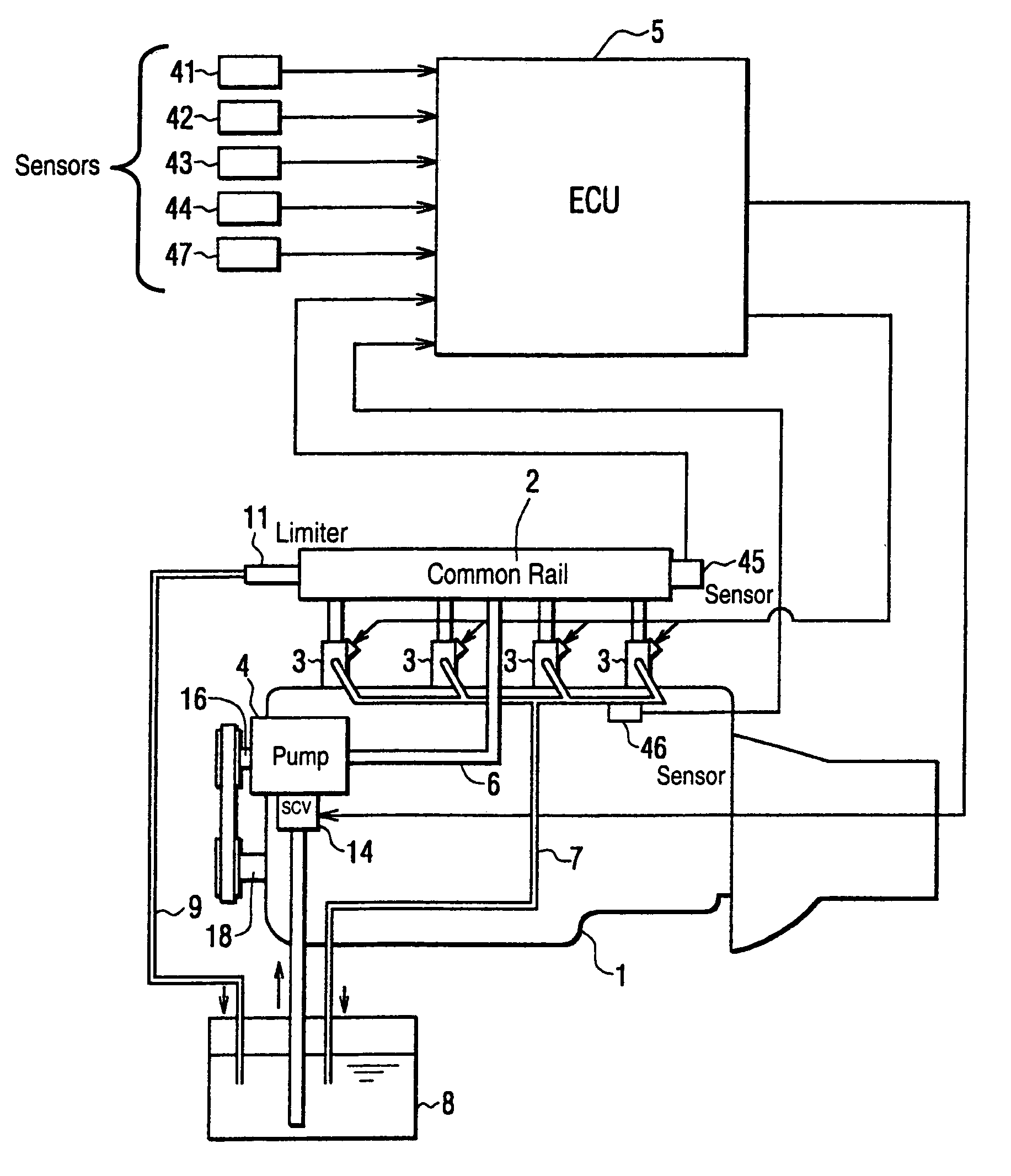
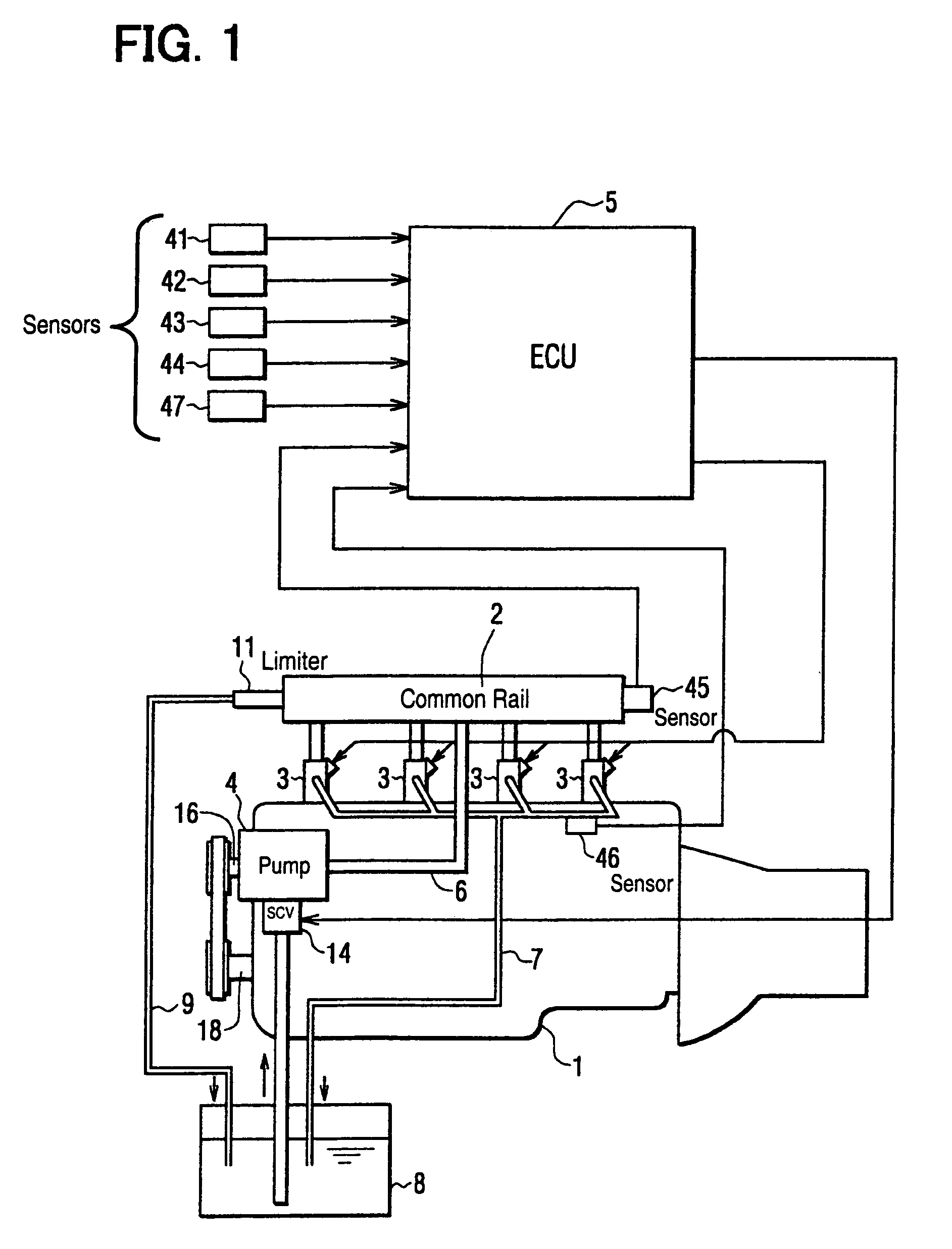
[0024]Referring to FIG. 1, a common rail type fuel injection system according to an embodiment of the present invention is illustrated. The fuel injection system shown in FIG. 1 injects fuel into a diesel engine 1. The fuel injection system includes a common rail 2, injectors 3, a supply pump 4, an engine control unit (ECU) 5 and the like.

[0025]The common rail 2 is an accumulation vessel for accumulating high-pressure fuel, which is to be supplied to the injectors 3. The common rail 2 is connected to a discharge hole of the supply pump 4, which discharges the high-pressure fuel, through a fuel pipe (a high-pressure fuel passage) 6. Thus, the common rail 2 can continuously accumulate a common rail pressure corresponding to a fuel injection pressure.

[0026]Leak fuel from the injectors 3 is returned to a fuel tank 8 through a leak pipe (a fuel return passage) 7.

[0027]A pressure limiter 11 as a safety valve is disposed in a relief pipe (a fuel return passage) 9 leading from the common r...


PUM


Abstract

When a pressure-feeding period of a supply pump and an injection period of an injector overlap and an actual injection quantity is affected by a pump pressure-feeding quantity of fuel supplied by the supply pump, an engine control unit (ECU) calculates the pump pressure-feeding quantity supplied during the injection period and calculates a correction value in accordance with the pump pressure-feeding quantity. The ECU corrects a command injection quantity with the correction value. Thus, even if injection start timing changes in accordance with a change in an operating state and if the pump pressure-feeding quantity supplied during the injection period changes because of the change in the injection start timing, variation in the actual injection quantity can be inhibited. As a result, the injector can inject an optimum quantity of the fuel.

Description

CROSS REFERENCE TO RELATED APPLICATION[0001]This application is based on and incorporates herein by reference Japanese Patent Application No. 2003-361091 filed on Oct. 21, 2003.BACKGROUND[0002]1. Field[0003]Exemplary embodiments of the present invention relate to a common rail type fuel injection system. Specifically, the present invention relates to correction control for correcting a change of an injection quantity of fuel injected from an injector, the change being caused by pump pressure-feeding operation (fuel pressure-feeding operation) of a supply pump.[0004]2. Description of Related Art[0005]In the case where pump pressure-feeding operation (fuel pressure-feeding operation) of a supply pump and a fuel injection of an injector are performed not on a one-on-one basis, a common rail pressure at the time when the injection is performed will vary among cylinders. As a result, an actual injection quantity of the fuel actually injected from the injectors will vary among the cylinde...

Claims


Application Information

Patent Timeline
Patent Type & Authority Patents(United States)
IPC IPC(8): F02D41/04F02M51/00F02D41/20F02D41/38F02D41/40F02D45/00F02M1/00F02M37/04
CPCF02D41/3836F02D41/3845F02D2250/04
Inventor SUENAGA, RYOOKI, NAMORU
Owner DENSO CORP
Learn More