Test tube carrier

Inactive Publication Date: 2005-12-06
THERMO ELECTRONICS OY
View PDF11 Cites 94 Cited by
  • Summary
  • Abstract
  • Description
  • Claims
  • Application Information

AI Technical Summary

Benefits of technology

[0011]The invention offers significant benefits.
[0012]A test tube carrier according to the invention has no loosely moving parts, whereby its wear in use and need for maintenance are minimal. As the structure has no loosely moving parts, it can be designed free from any recesses or holes capable of accumulating contaminating material. Accordingly, the test tube carrier is easy to clean and keep in a hygienic condition. The test tube carrier operates problem-free at all times and possible damage in its structure is instantly visible. The base part of the test tube carrier can be manufactured advantageously by injection molding without any need for post-machining, and the device is extremely simple to produce by manual techniques or in automatic assembly systems. The test tube carrier operates reliably over a large range of test tube/vial sizes and the

Problems solved by technology

The above-kind of test tube carrier, however, is hampered by plural disadvantages.
Due to incorporating loosely moving members, difficult-to-clean recesses that may accumulate sample material and other impurities are formed, e.g., in the holes and control grooves of the steel-wire retainer members of the carrier base.
As a result, the structure has a higher need for aggressive washing and disinfection, whereby the washing step becomes extremely arduous especially for the O-ring that must be replaced from time to time due to aging.
If the compressive force exerted by the ring is lost or the ring breaks up, the test tubes will not stay upright at all on the test tube carrier.
If the test tube flips aside during transport, the moving carriers contaminate the transport system over a large area, whereby a long shutdown is necessary for cleaning.
The machining of the drilled holes and arcuate control grooves need two cutting steps per each steel-wire retainer member and, furthermore, an unnecessarily complicated casting mold for making the carrier base.
The use of elongated steel-wire retainer members adapted to conform with the exterior surface of a test tube

Method used


Image

  • Test tube carrier
  • Test tube carrier
  • Test tube carrier

Examples


Embodiment Construction

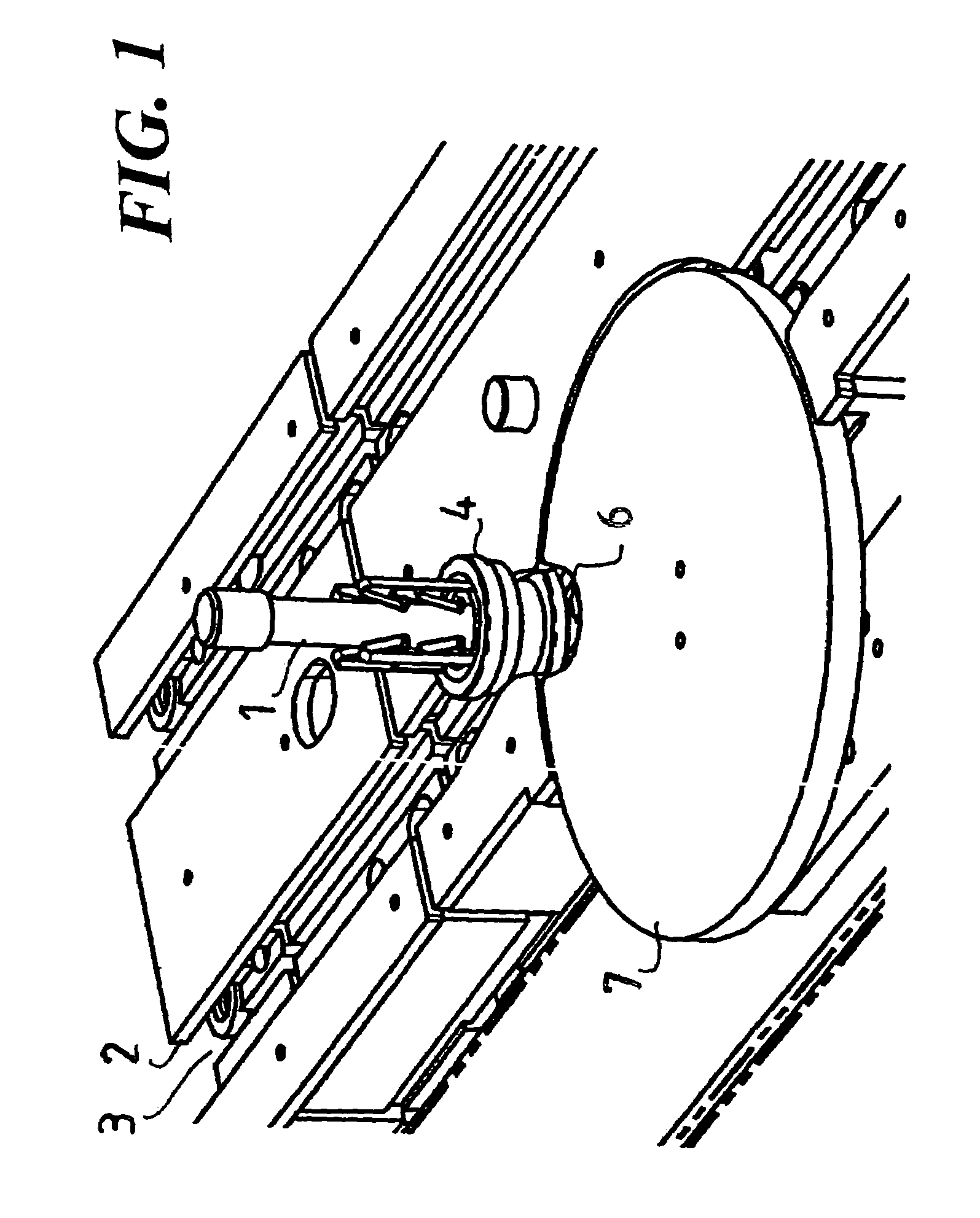
[0019]Referring to FIG. 1, therein is shown a portion of a transport system suited for moving test tubes 1 placed on test tube carriers 4 between different handling stations. The transport system comprises a guide lane 3 forming a transport path for the test tube carriers 4 and having rails 2 at its sides for supporting the test tube carriers during their travel and preventing the same from tipping aside. At the bottom of the guide lane 3 are provided running belts 5 (not shown) on which the test tube carriers move supportedly. The guide lane 3 forming the transport path controls the transport route of a given test tube carrier 4. Operating along the path of the guide lane are adapted handling stations capable of performing analysis of a sample contained in a test tube, rearrangement of the sample sequence and other possible functions such as derouting to a crossing lane. In the transport system of FIG. 1, the handling station shown therein includes a turnstile disc 7 with a transfe...


PUM


Abstract

The invention relates to a test tube carrier (4) for transporting test tubes in a transport system, said carrier (4) comprising a base (8) having a recess made thereto for accommodating the bottom of a test tube/vial (1), and support members (9, 10) adapted to the carrier base (8) for clamping a test tube (1) inserted in said recess and supporting the same. The support members (9, 10) are permanently affixed to said carrier base (8) and comprise elongated portions with their free ends bent toward the vertical center axis of the carrier base and said upper ends providing a support surface (22) for making supportive contact to the test tube. The bottom of the carrier base recess for accommodating a test tube is advantageously made flat and the carrier base is provided with test tube support members whose support surfaces (22) extend to at least two different heights from the top level of the carrier base (8).

Description

[0001]This application is the national phase under 35 U.S.C. § 371 of PCT International Application No. PCT / FI02 / 00287 which has an International filing date of Apr. 3, 2002, which designated the United States of America.BACKGROUND OF THE INVENTION[0002]1. Field of the Invention[0003]The invention relates to a test tube carrier according to the preamble of claim 1 for transporting different kinds of test tubes in sample analysis systems and other kinds of automatic specimen handling systems, wherein individual test tubes / vials are moved between separate stations.[0004]2. Description of Background Art[0005]These kinds of test tube carriers are conventionally used for transporting samples to be analyzed for probing at different analyzer stations. The sample transport system comprises a conveyor lane for moving the transport carriers and a number of carrier handling points, wherein the carrier with its test tube(s) can be moved to a sample probing point, a queue thereof or to a buffer ...

Claims


Application Information

Patent Timeline
IPC IPC(8): G01N35/04
CPCG01N35/04
Inventor HASSINEN, MATTIKORHONEN, JUHAKAARAKAINEN, KEIJOMALLENIUS, ATTE
Owner THERMO ELECTRONICS OY
Why Eureka
Try Eureka