Multi-laser beam welding high strength superalloys

a superalloy and multi-laser beam technology, applied in the direction of heat treatment equipment, turbines, furnaces, etc., can solve the problems of increasing the cost of current turbine blades, increasing the cost of superalloy welds, and increasing the cost of superalloy materials. , to achieve the effect of reducing or eliminating weld-induced damage and cost saving

Inactive Publication Date: 2005-12-06
HONEYWELL INT INC
View PDF12 Cites 61 Cited by
  • Summary
  • Abstract
  • Description
  • Claims
  • Application Information

AI Technical Summary

Benefits of technology

[0012]The present invention provides a method for repairing superalloy turbine blades and vanes. The method uses multiple lasers to perform a heating step and / or a cladding step and / or a post-welding heating step. This method can use multiple lasers to create a highly localized area of heating that either reduces or eliminates weld-induced damage or hot cracking formation. The method allows repaired turbine blades to return to service and therefore offers considerable cost savings over the replacement alternative.

Problems solved by technology

An economic consequence of such a design criteria is that currently used turbine blades can be quite expensive.
Disadvantageously, the superalloys generally are very difficult to weld successfully.
Traditional repair methods have proven less satisfactory for superalloy materials.
However, during such a high temperature welding, the turbine blade may experience severe oxidation, giving the blade undesired properties for further engine service.
This treatment may heat the welded workpiece to a given temperature level, and cause severe cracking due to residual stress relief and gamma prime precipitation.
The option of throwing out worn turbine blades and replacing them with new ones is not an attractive alternative.
The blades are extremely expensive due to costly material and manufacturing process.
A high pressure turbine blade made of superalloy can be quite costly to replace, and a single stage in a gas turbine engine may contain several dozen such blades.

Method used


Image

  • Multi-laser beam welding high strength superalloys
  • Multi-laser beam welding high strength superalloys
  • Multi-laser beam welding high strength superalloys

Examples


Embodiment Construction

[0025]Reference will now be made in detail to exemplary embodiments of the invention, examples of which are illustrated in the accompanying drawings. Wherever possible, the same reference numbers will be used throughout the drawings to refer to the same or like parts.

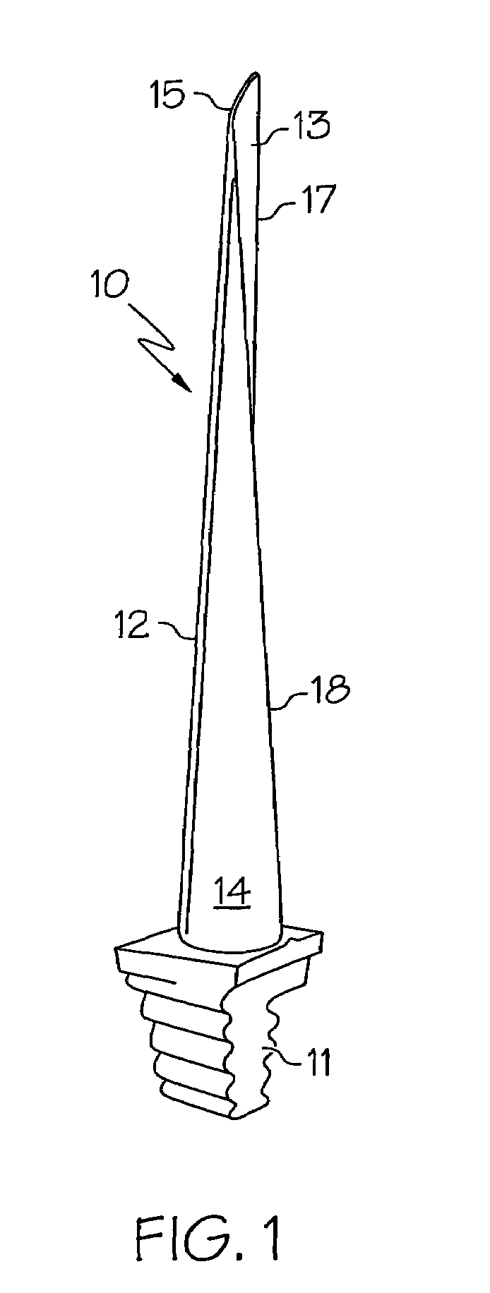
[0026]A typical gas turbine blade 10 is illustrated in FIG. 1. Such a blade has different geometry and dimension designs, depending on engine model and its application. For a typical aero-engine, a turbine blade is typically several inches in length. A gas turbine blade includes a serrated base assembly 11, also called a mounting dovetail, tang, or christmas tree, where the blade is affixed to a hub (not shown). In a jet engine assembly multiple such turbine blades are positioned in adjacent circumferential position along a hub or rotor disk. Airfoil 12, a cuplike structure, includes a concave face 13 and a convex face 14. In the literature of turbine technology airfoil 12 may also be referred to as a bucket. Airfoil 12...


PUM

PropertyMeasurementUnit
distanceaaaaaaaaaa
poweraaaaaaaaaa
diameteraaaaaaaaaa

Abstract

A method is provided for repairing degraded and / or eroded areas on gas turbine blades and vanes. The method is directed to turbine blades and vanes made of advanced superalloy materials with high elevated-temperature properties. The method uses multiple laser beams to perform steps of preheating the repair area, welding the repair area, and post-welding heating of the repaired area. The method uses an array of two or more lasers to perform the steps of heating, welding, and post-weld heat treatment in nearly simultaneous operation thereby dramatically reducing or eliminating the hot cracking associated with other welding methods used with superalloy materials. The method is further directed to cladding or material buildup of degraded turbine blades where the weld material is the same as the matrix or better superalloy materials.

Description

FIELD OF THE INVENTION[0001]The present invention relates to laser powder fusion welding of metallic materials. More particularly the invention relates to laser welding methods using multiple laser beams to repair gas turbine engine components such as turbine blades and vanes.BACKGROUND OF THE INVENTION[0002]In an attempt to increase the efficiencies and performance of contemporary gas turbine engines generally, engineers have progressively pushed the engine environment to more extreme operating conditions. The harsh operating conditions of high temperature and pressure that are now frequently specified place increased demands on engine component-manufacturing technologies and new materials. Indeed the gradual improvement in engine design has come about in part due to the increased strength and durability of new materials that can withstand the operating conditions present in the modern gas turbine engines. With these changes in engine materials, there has arisen a corresponding nee...

Claims


Application Information

Patent Timeline
Patent Type & Authority Patents(United States)
IPC IPC(8): B23K26/34
CPCB23K26/032B23K26/0604B23K26/0853B23K26/1411B23K26/3286B23K26/34B23K26/421B23P6/007C21D9/50F01D5/005B23K26/3206B23K26/3213B23K26/345C22F1/10B23K2201/001F05D2230/31B23K26/32B23K26/342B23K26/144B23K26/60B23K2101/001B23K2101/35B23K2103/26B23K2103/50
Inventor HU, YIPINGHEHMANN, WILLIAM F.
Owner HONEYWELL INT INC
Why Eureka
Try Eureka