Vibration mirror, optical scanning device, and image forming using the same, method for making the same, and method for scanning image

a technology of optical scanning and vibration mirrors, applied in the field of vibration mirrors, optical scanning devices, and image forming using the same, can solve the problems of image degradation, large driving torque, and large vibration angle, and achieve the effects of reducing processing time, reducing vibration mirror weight, and simplifying the process

Inactive Publication Date: 2005-12-06
RICOH KK
View PDF18 Cites 48 Cited by
  • Summary
  • Abstract
  • Description
  • Claims
  • Application Information

AI Technical Summary

Benefits of technology

[0014]According to the foregoing description, an object of this invention is to provide a vibration mirror and a method for making the same. The vibration mirror has a structure capable of simplifying a process to form a recess part for reducing weight of the vibration mirror and also for reducing a processing time.
[0015]It is another object of this invention to provide an optical scanning device with a simple structure, a large vibration angle for performing a scanning process, a low driving voltage, a highly improved reliability, a strong strength, a high yield rate and a low cost, and a method for making the optical scanning device.
[0016]It is another object of this invention to provide an image forming device with the aforementioned optical scanning device, capable of performing an optical writing in an electrophotographic process with a high accuracy and a high speed. The image forming device can reduce an amount of parts used and its manufacturing cost
[0017]It is still another object of this invention to provide an reading device with the aforementioned optical scanning device with a high accuracy and a high speed. The image forming device can reduce an amount of parts used and its manufacturing cost
[0018]It is still another object of this invention to provide a scanning control device or method capable of reducing image degradation due to a driving error of a deflection means (a vibration mirror). In addition, a program, a positioning mechanism, an optical scanning unit and an image forming device using the same capable of reducing image degradation are provided.

Problems solved by technology

However, the thickness of the movable mirror made by the above manner is entirely uniform, and if the thickness of the first silicon substrate of the SOI substrate is directly used as the thickness of the movable mirror, the momentum of inertia of the movable mirror is large and the vibration angle is large, so that a large driving torque is required.
For obtaining a desired vibration angle, the only way is to increase the driving voltage and enlarge the electrostatic torque Tq, so that there are limitations.
In particular, for an image forming device to form one image by overlapping images that are recorded by plural optical scanning devices, image degradation is a severe problem.

Method used


Image

  • Vibration mirror, optical scanning device, and image forming using the same, method for making the same, and method for scanning image
  • Vibration mirror, optical scanning device, and image forming using the same, method for making the same, and method for scanning image
  • Vibration mirror, optical scanning device, and image forming using the same, method for making the same, and method for scanning image

Examples


Embodiment Construction

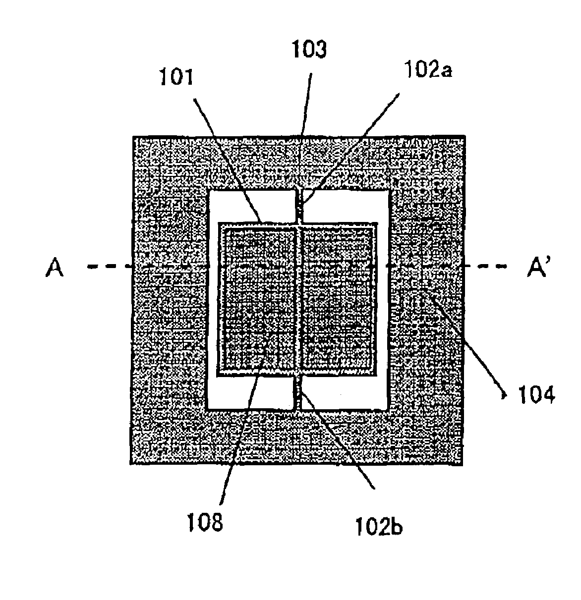
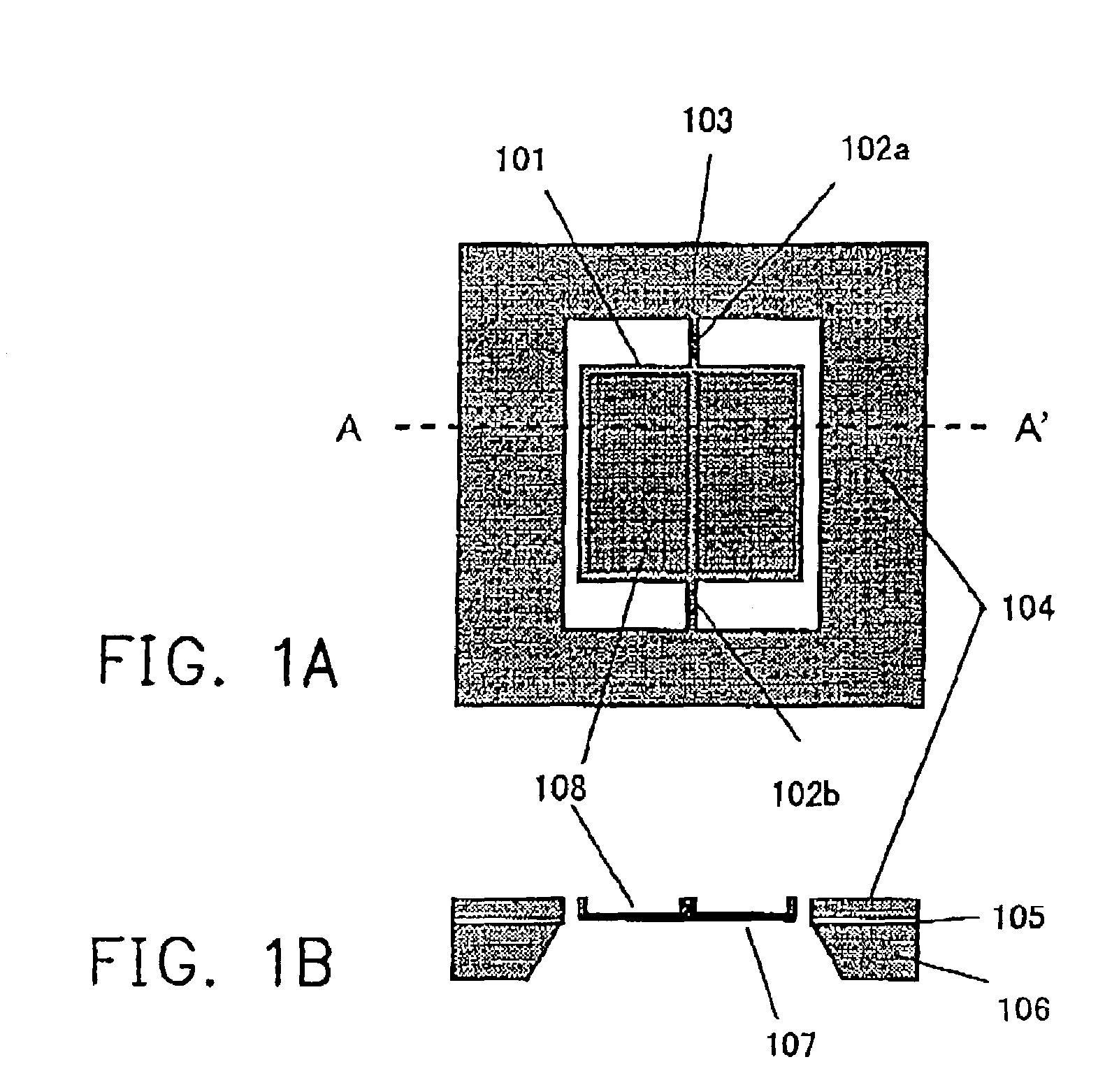
[0099]The embodiments of the present invention are described in detail accompanying with the attached drawings. FIGS. 1A and 1B show an embodiment of a vibration mirror according to the present invention. FIG. 1A is a schematic view showing the shape of the vibration mirror, when viewed from an opposite side to a mirror surface on the vibration mirror. FIG. 1B shows schematically a cross-sectional view along the line A—A in FIG. 1A.

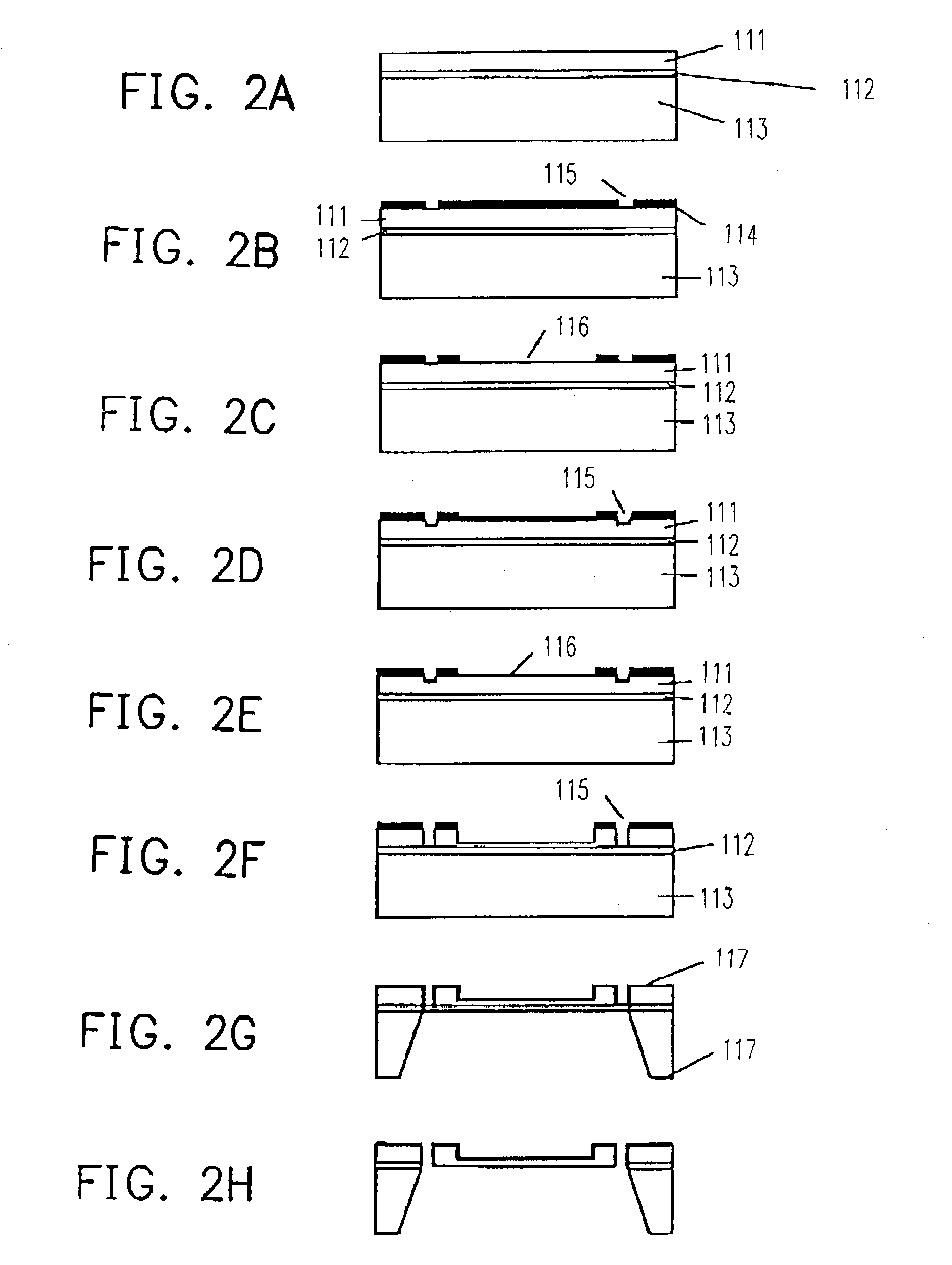
[0100]The vibration mirror uses a three-layered substrate where a silicon substrate 104 (as a first substrate) and a silicon substrate 106 (as a second substrate) are jointed through an oxide layer 105 as an insulating layer, and is made by using the micro machining technology. The exemplary manufacturing process is described in detail as follows.

[0101]The vibration mirror comprises a movable mirror 101, torsional rods 102a, 102b, and a supporting frame 103. The movable mirror 101 is entirely a quadrate or rectangular in shape. Central parts of opposite s...


PUM


Abstract

A vibration mirror is reciprocatively vibrated by an electrostatic force to reflect an incident light beam. The vibration mirror comprises a reflection means for reflecting the incident light beam; a reflection means holding substrate for holding the reflection means; a torsional rotation shaft comprising rod members rotatably supporting two ends of the reflection means holding substrate; movable electrodes formed on side faces of the reflection means holding substrate supported; a first substrate for supporting the reflection means supporting substrate via the torsional rotation shaft; first fixed electrodes formed on the first substrate so as to face the movable electrodes; a first electrically insulating and separating means formed on the first substrate to electrically insulate and separate the movable electrodes from the first fixed electrodes; and a second substrate overlaid on the first substrate with an insulating layer therebetween so as to be electrically insulated from and overlapped to adhere onto the first substrate.

Description

CROSS-REFERENCE TO RELATED APPLICATION[0001]This application claims the priority benefit of Japanese applications, under serial nos. 2002-039279, filed on Feb. 15, 2002; 2002-125750, filed on Apr. 26, 2002; 2002-057428, filed on Mar. 4, 2002.BACKGROUND OF THE INVENTION[0002]1. Field of the Invention[0003]This invention relates in general to an optical scanning device, a scanning control device for controlling the optical device, a program used by a computer for executing a scanning control, a positioning mechanism for positing the optical scanning device within an image forming device, an optical scanning unit with a plurality of optical scanning devices, and an image forming device or a read device using the optical scanning device. In particular, the invention relates to a vibration mirror used for the optical scanning device and a method for making the vibration mirror.[0004]2. Description of the Related Art[0005]In a conventional optical scanning device, a mirror substrate, whic...

Claims


Application Information

Patent Timeline
Patent Type & Authority Patents(United States)
IPC IPC(8): B41J2/47B81B3/00G02B26/08G02B26/10G06K7/10
CPCB41J2/471G02B26/0841G02B26/0858G02B26/101G06K7/10653Y10S359/90
Inventor FUJII, MITSUMISATOH, YUKITONAKAJIMA, TOMOHIRO
Owner RICOH KK
Why Eureka
Try Eureka