Cycle slip detection using low pass filtering

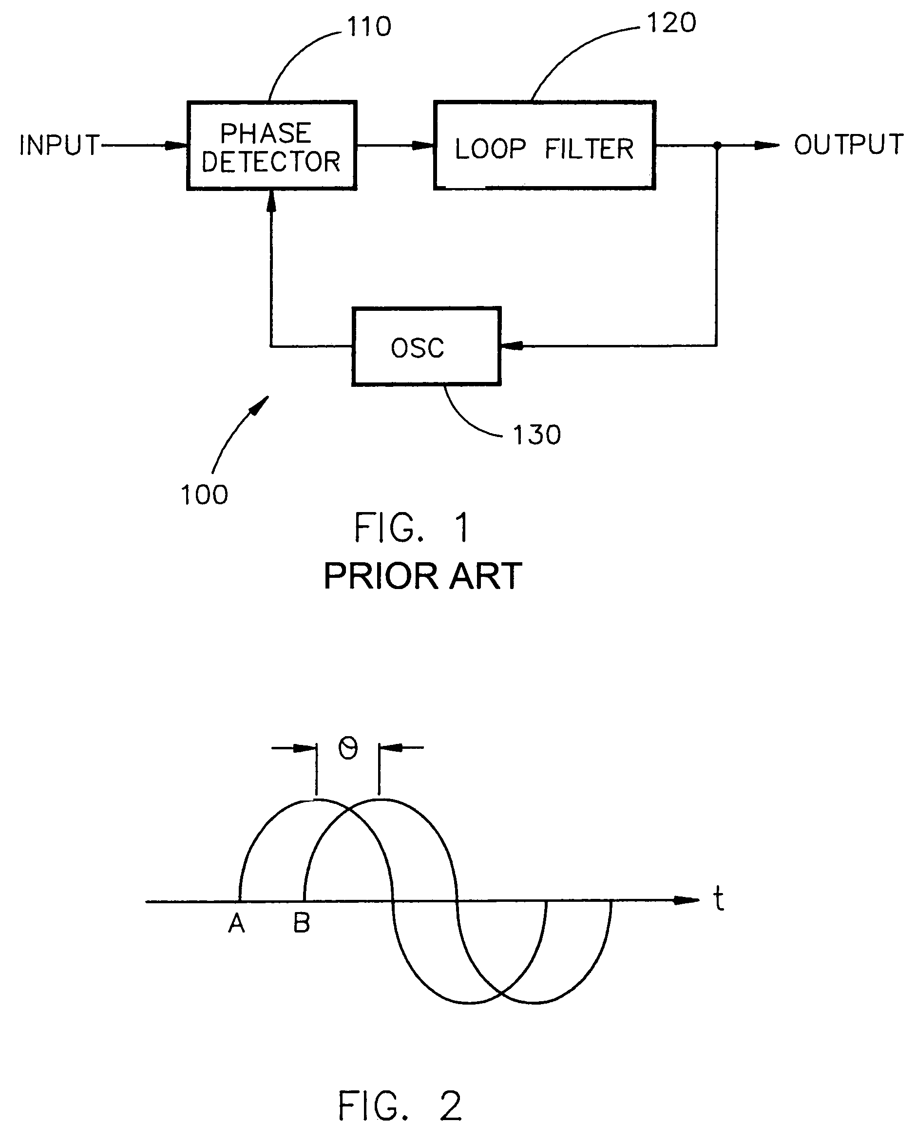
a low-pass filtering and cycle slip detection technology, applied in the direction of digital transmission, pulse automatic control, transmission, etc., can solve the problems of inconvenient cycle slip detection output inconvenient operation of loop filter b>120/b>, and inability to accurately calculate pseudoranges

Inactive Publication Date: 2005-12-06
ROCKWELL COLLINS INC
View PDF15 Cites 43 Cited by
  • Summary
  • Abstract
  • Description
  • Claims
  • Application Information

AI Technical Summary

Benefits of technology

[0020]A cycle slip detector adapted for use in a phase comparison circuit is provided according to one embodiment of the invention. The cycle slip detector comprises a cycle slip detection filter possessing a predetermined filter bandwidth and a predetermined high frequency cut-off. The cycle slip detection filter receives a phase difference generated by the phase comparison circuit and transforms the phase difference into a filtered phase difference. The cycle slip detector further comprises a compensator communicating with the cycle slip detection filter. The compensator compensates the magnitude based on a predetermined compensation response. The cycle slip detector further comprises a cycle slip occurrence detector communicating with the compensator. The cycle sl

Problems solved by technology

Therefore, if the clock in the receiver does not accurately track the clock in the transmitting satellite, the accuracy of the calculated pseudorange will be compromised and the range determination will be inaccurate.
However, the output of the loop filter 120 is not generally suitable for cycle slip detection.
If the phase excursions are large enough and occur rapidly enough, a cycle slip can occur.
Therefore, the tracking may slip one or more cycles from the input (carrier) waveform A, and may slip ahead of or behind the input waveform A. As a result, in applications where a cycle count is important (such as in GPS type systems) or where cycle slips affect accuracy of the data output, cycle slips become troublesome.
It is known in the art that cycle slips can occur and can affect accuracy of communication systems employing phase angle tracking.
One condition is when ambient noise interferes wi

Method used


Image

  • Cycle slip detection using low pass filtering
  • Cycle slip detection using low pass filtering
  • Cycle slip detection using low pass filtering

Examples


second embodiment

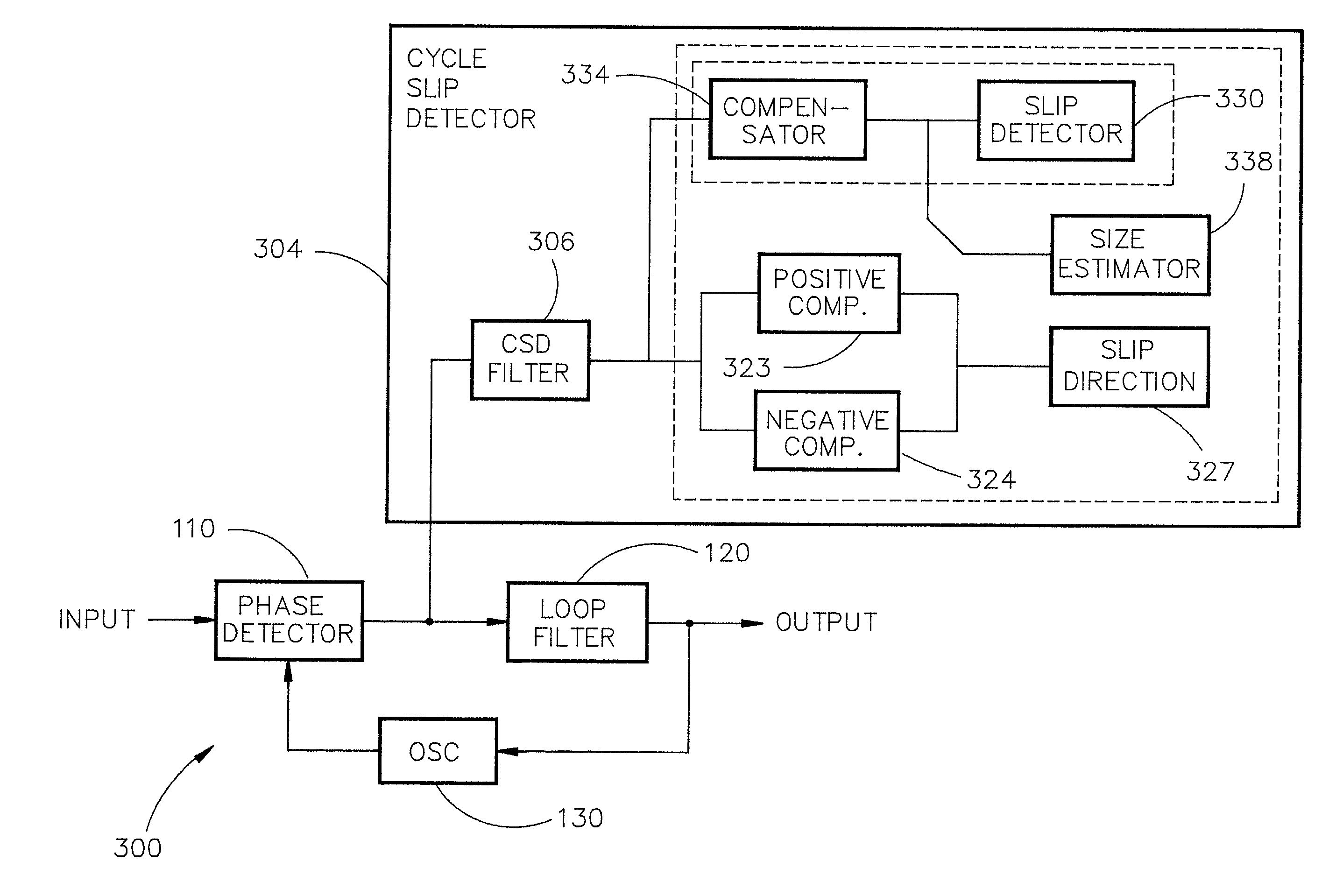
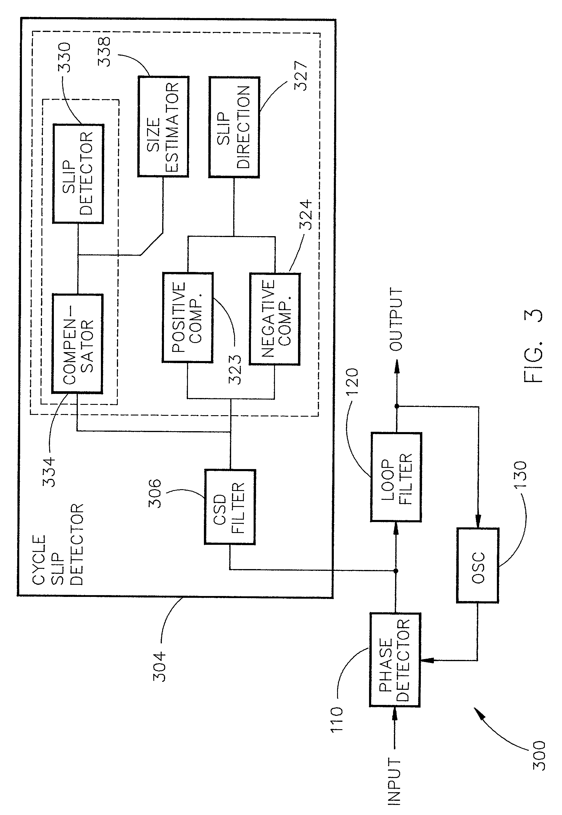
[0040]The positive comparator 323 and the negative comparator 324 detect positive and negative peaks in a bipolar pulse, such as that shown in FIG. 6. If the peaks exceed positive and negative cycle slip thresholds, positive and negative cycle slip outputs are generated by the positive comparator 323 and the negative comparator 324 respectively. The second embodiment further includes a cycle slip direction detector communicating with the positive comparator and the negative comparator. The cycle slip direction detector receives the positive and negative cycle slip outputs. The cycle slip direction detector generates a positive cycle slip output if a positive bipolar pulse peak occurs first in the bipolar pulse and if the bipolar pulse frequency is within a predetermined mid-frequency range. Conversely, the cycle slip direction detector generates a negative cycle slip output if a negative bipolar pulse peak occurs first in the bipolar pulse and if the bipolar pulse frequency is withi...

first embodiment

[0074]FIG. 9 is a flow chart 900 of a cycle slip detection method according to the invention. In step 903, a phase difference output from a PLL is filtered. The filtering removes high frequency signal components present in the phase difference due to noise and / or vehicle dynamics. The low or band-pass filtering is performed because the low frequency region of the phase difference output does not cause cycle slips, the mid-frequency region can cause cycle slips, and the high frequency region contains strong noise bursts.

[0075]In step 909, the filtered phase difference is used to detect a cycle slip. In one embodiment of the detection step, a cycle slip is detected in the filtered phase difference and a cycle slip output is therefore generated if a filtered phase difference magnitude exceeds a predetermined cycle slip threshold.

[0076]In another embodiment of the detection step, the magnitude of the filtered phase difference is compensated, based on a predetermined compensation respons...


PUM


Abstract

A cycle slip detector and detection method for a phase comparison circuit are provided. The cycle slip detector includes a cycle slip detection filter possessing a predetermined filter bandwidth and a predetermined high frequency cut-off. The cycle slip detection filter receives a phase difference generated by the phase comparison circuit and transforms the phase difference into a filtered phase difference. The cycle slip detector further includes a compensator communicating with the cycle slip detection filter. The compensator compensates the magnitude based on a predetermined compensation response. The cycle slip detector further includes a cycle slip occurrence detector communicating with the compensator. The cycle slip occurrence detector compares a compensated magnitude of the filtered phase difference to a predetermined cycle slip threshold and generates a cycle slip output if the compensated magnitude exceeds the predetermined cycle slip threshold.

Description

FIELD OF THE INVENTION[0001]The present invention relates generally to a cycle slip detector, and more particularly to a cycle slip detector capable of providing a cycle slip detection and an estimation of cycle slip size.BACKGROUND OF THE INVENTION[0002]Modern electronic communications rely highly on communication systems that employ some sort of phase tracking. Electronic communication systems may be employed for a wide variety of needs including voice and data communications, positioning systems, etc.[0003]One of the more common applications for digital data communications are positioning systems, such as the global positioning system (GPS) constructed for the U.S. armed services. There are other such systems around the world, but the discussion will hereinafter refer only to the GPS system. These positioning systems include satellite constellations that may be used to perform a triangulation of a corresponding receiver anywhere on the earth. This triangulation yields not only a ...

Claims


Application Information

Patent Timeline
IPC IPC(8): H03L7/095H04L7/00H04L25/00
CPCH03L7/095
Inventor THURINGER, DANIEL J.
Owner ROCKWELL COLLINS INC
Why Eureka
Try Eureka