Autoprotected optical communication ring network

a technology of optical communication ring network and autoprotection, which is applied in the field of optical communication system, can solve the problems of not being able to protect more than n channels, not being able to have different protection mechanisms, and being unable to protect the other working channels temporarily, so as to avoid sudden power variations inside the network

Inactive Publication Date: 2005-12-06
CISCO TECH INC
View PDF12 Cites 38 Cited by
  • Summary
  • Abstract
  • Description
  • Claims
  • Application Information

AI Technical Summary

Benefits of technology

[0022]Since the reconfiguration takes place at the channel level instead of at the multiplex section level, there is no need to provide each node with a switching equipment to perform protection on all the network channels (in particular, it is then not necessary to use a complex switch matrix as in the Optical Multiplex Section Shared Protection scheme).
[0023]Unlike the Optical Multiplex Section Shared Protection scheme proposed in U.S. Pat. No. 5,647,035, the complexity of the node switching structure depends only on the nu

Problems solved by technology

It is observed that, although this method provides a double capacity with respect to the previous technique, with N wavelengths it is still not possible to protect more than N channels.
Additionally, under this approach, it is not possible to have different protection mechanisms (i.e., protection at different layers) for different channels, and that the optical path after a protection reconfiguration can be longer than the ring circumference.
Furthermore, it is observed that in the Optical Multiplex Section Shared Protection, because the failure control is performed at the multiplex section level, a failure on a single optical channel (e.g., when a node transmitter is damaged) may be either ignored or may cause the reconfiguration of all the traffic, the

Method used


Image

  • Autoprotected optical communication ring network
  • Autoprotected optical communication ring network
  • Autoprotected optical communication ring network

Examples


Embodiment Construction

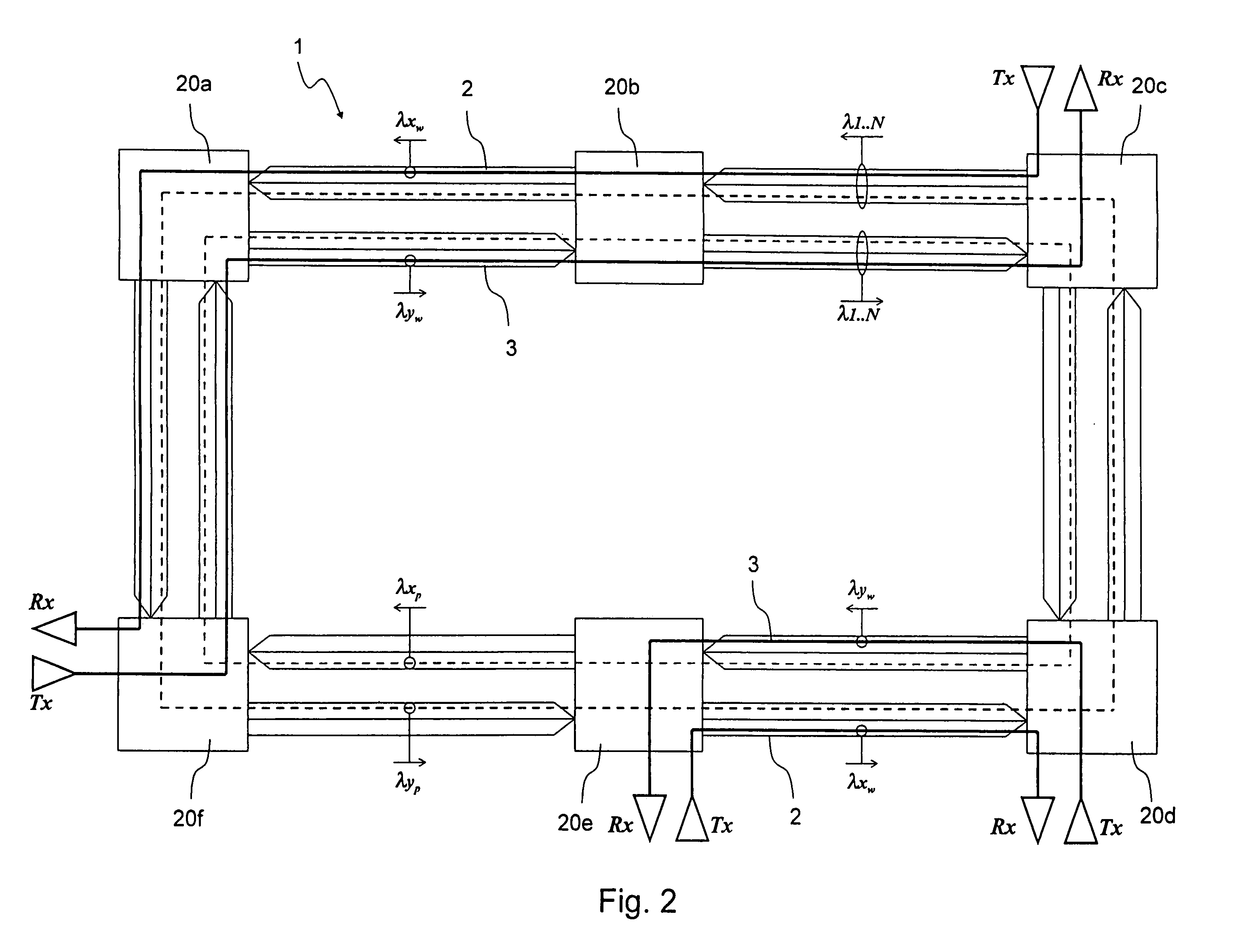
[0059]Schematically shown in FIG. 2 is an optical communication ring network 1 according to an embodiment of the present invention. Network 1 includes a first and a second optical fiber ring 2, 3 defining respective optical carriers that have opposite transmission directions. The network 1 also includes a plurality of nodes 20a–20f, which are positioned along the first and the second ring 2, 3, for adding and dropping optical signals. Network 1 is adapted for both terrestrial transmissions and transoceanic transmissions. For long-haul transmissions, in particular, transoceanic transmissions, network 1 is preferably provided with line optical amplifiers and / or boosters and / or preamplifiers (not shown).

[0060]In FIG. 2, rings 2, 3 define an external ring having a counter-clockwise transmission direction and an internal ring with a clockwise transmission direction, respectively. The number of nodes in network 1, by way of example, is six; however, the present invention has applicability...


PUM


Abstract

An autoprotected optical communication ring network is disclosed. The ring network includes two optical carriers that are arranged for bidirectional transmission. Multiple optically reconfigurable nodes are connected along the optical carriers. The nodes communicate in pairs, defining non-overlapping working links. Under normal conditions, the nodes of each pair are optically configured to exchange optical signals over the working link at a first wavelength on the first carrier and at a second wavelength that is different from the first wavelength on the second carrier. During a failure condition, the first wavelength on the second carrier and the second wavelength on the first carrier are reserved for effecting a protection scheme, while the first wavelength on the first carrier and the second wavelength on the second carrier can still be used for unaffected working links.

Description

CROSS-REFERENCE TO RELATED APPLICATIONS[0001]This application is related to and claims benefit of priority to (i) European Patent Application No. 991125527.7, filed Jul. 1, 1999 and (ii) U.S. Provisional Patent application Ser. No. 60 / 142,534, filed Jul. 7, 1999, entitled “AUTOPROTECTED OPTICAL COMMUNICATION RING NETWORK”.BACKGROUND OF THE INVENTION[0002]1. Field of the Invention[0003]The present invention relates to an optical communication system, and more particularly to a WDM (Wavelength Division Multiplexing) autoprotected optical communication ring network.[0004]“Optical communication ring network” as used herein refers not only to an entire communication network that is configured as a ring, but in general, any section of a network that comprises a plurality of nodes and branches, and that is arranged, at least temporarily, in a ring configuration.[0005]“Failure” as used herein refers to any event or condition which may affect the physical optical carriers (e.g., breakage or ...

Claims


Application Information

Patent Timeline
IPC IPC(8): H04B10/00H04B10/08H04B10/14H04B10/24H04J14/02
CPCH04B10/032H04J14/0283H04J14/0295
Inventor ARECCO, FULVIOVISCARDI, VALERIO
Owner CISCO TECH INC
Why Eureka
Try Eureka