
Temperature-based cooling device controller apparatus and method

a controller and temperature-based technology, applied in the field of thermoelectric sensing, can solve problems such as the halting of the system clock operation, and achieve the effects of increasing the system clock frequency, and reducing the clock frequency

Inactive Publication Date: 2005-12-13
INTEL CORP
View PDF124 Cites 76 Cited by
  • Summary
  • Abstract
  • Description
  • Claims
  • Application Information

AI Technical Summary

Benefits of technology

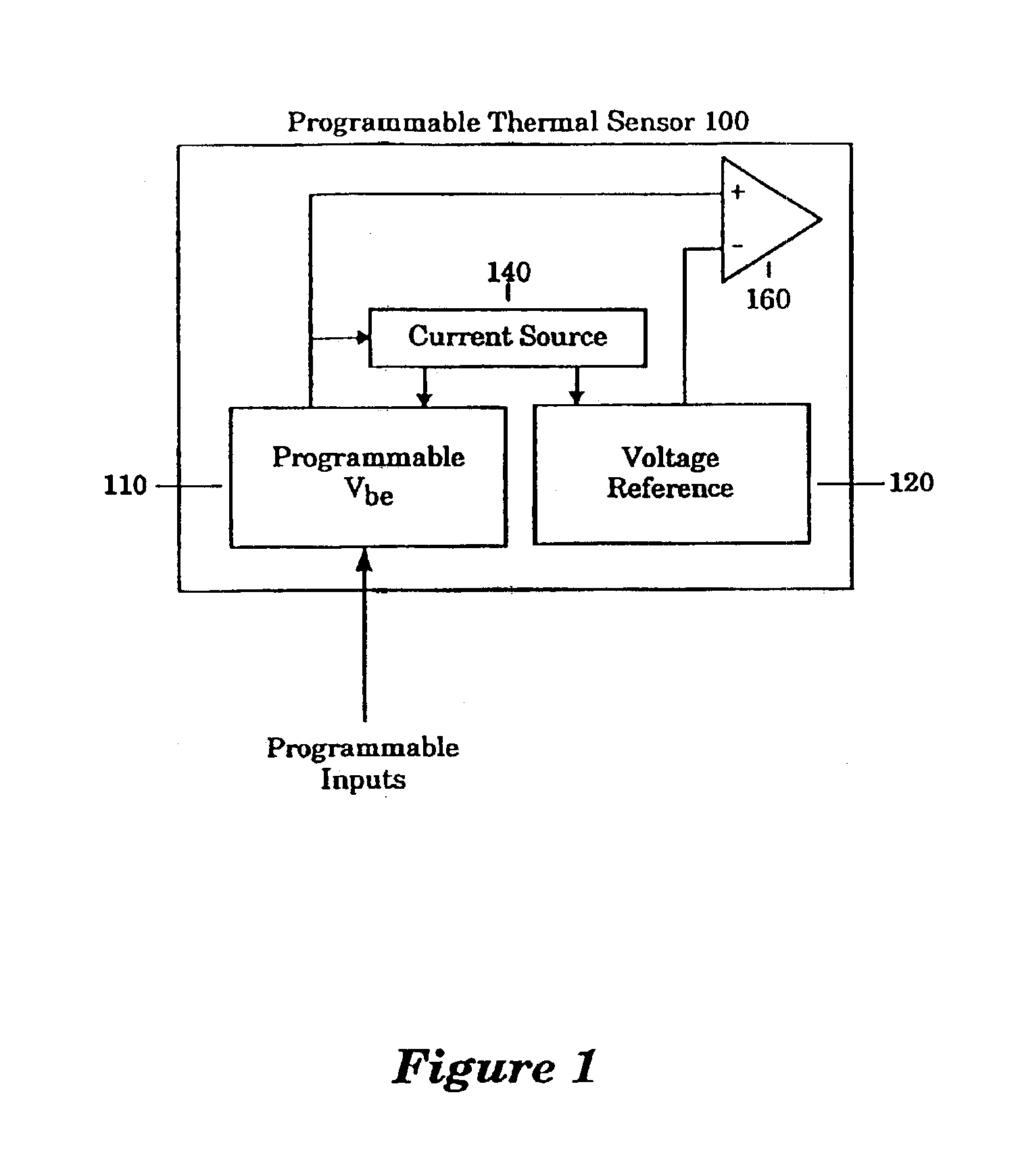
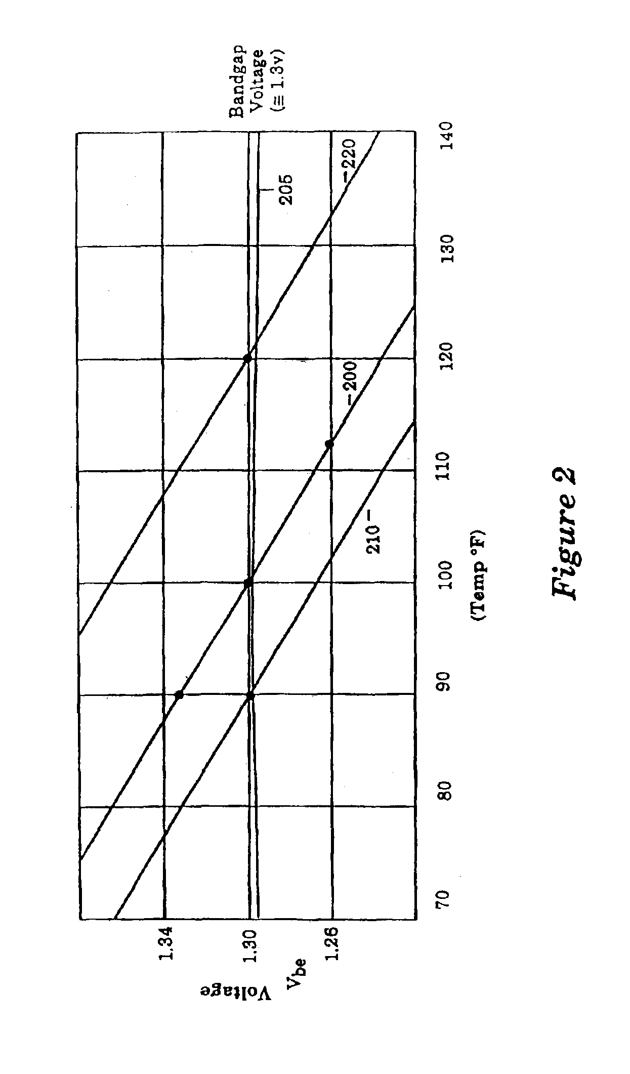
[0006]A programmable thermal sensor is implemented in an integrated circuit. The programmable thermal sensor monitors the temperature of the integrated circuit, and generates an output to indicate that the temperature of the integrated circuit has attained a predetermined threshold temperature. The programmable thermal sensor contains a voltage reference, a programmable Vbe, a current source, and a sense amplifier or comparator. The current source generates a constant current to power the voltage reference and the programmable Vbe. With a constant current source, the voltage reference generates a constant voltage over varying temperatures and power supply voltages. In a preferred embodiment, the voltage reference is generated with a silicon bandgap reference circuit. The constant voltage from the voltage reference is one input to the sense amplifier. The programmable Vbe contains a sensing portion and a multiplier portion. In general, the programmable Vbe generates a voltage dependent upon the temperature of the integrated circuit and the value of programmable inputs. The programmable inputs are supplied to the multiplier portion to generate a multiplier value for use in the multiplier portion. The voltage reference is compared with the voltage generated by the programmable Vbe in the sense amplifier. The sense amplifier generates a greater than, less than, signal.
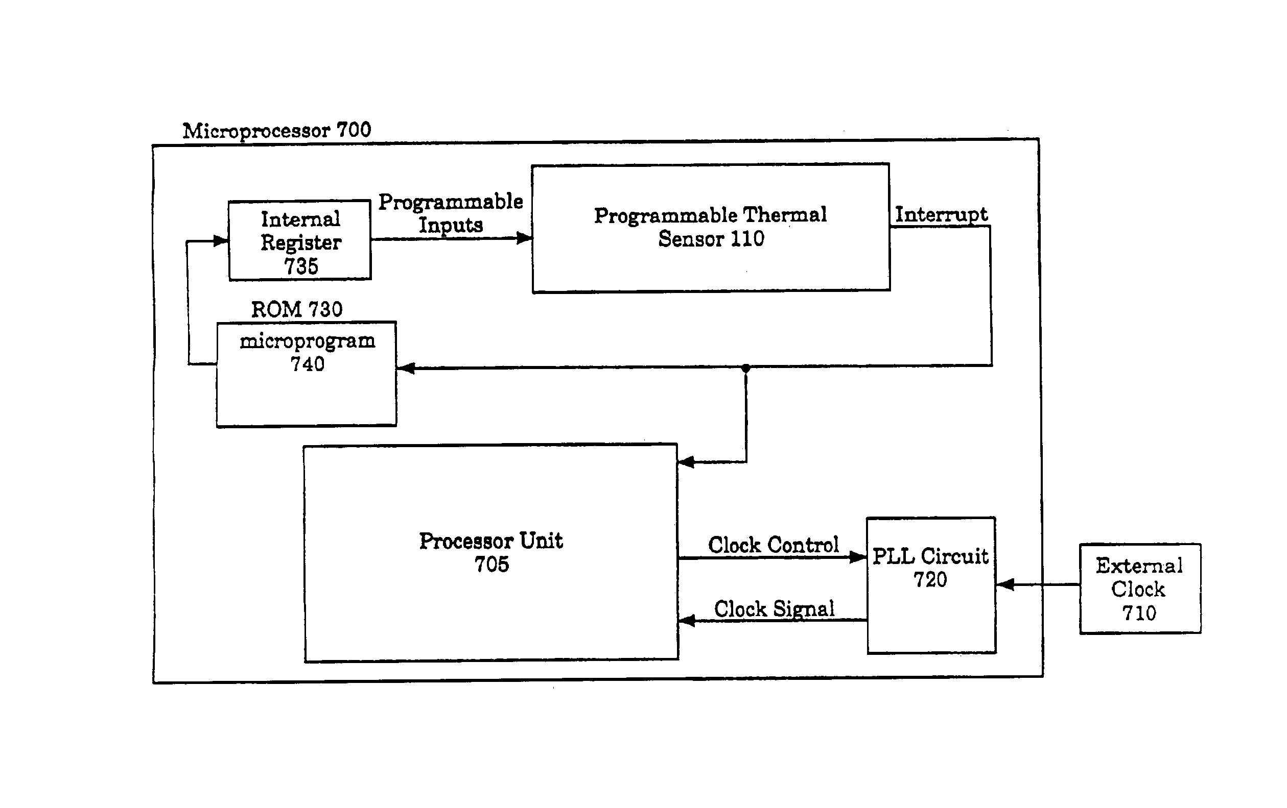
[0007]The programmable thermal sensor of the present invention is implemented in a microprocessor. In addition to the programmable thermal sensor, the microprocessor contains a processor unit, an internal register, microprogram and clock circuitry. The processor unit incorporates the functionality of any microprocessor circuit. The clock circuitry generates a system clock for operation of the microprocessor. In general, the microprogram writes programmable input values to t

Problems solved by technology

The fail safe thermal sensor generates an interrupt when detecting that the microprocessor reaches predetermined threshold temperatures and subsequently halts operation of the system clock.

Method used


Image

  • Temperature-based cooling device controller apparatus and method
  • Temperature-based cooling device controller apparatus and method
  • Temperature-based cooling device controller apparatus and method

Examples


first embodiment

[0045]Referring to FIG. 7, a microprocessor incorporating a programmable thermal sensor configured in accordance with the present invention is illustrated. A microprocessor 700 contains, in part, the programmable thermal sensor 100 and a processor unit 705. The processor unit 705 is intended to present a broad category of microprocessor circuits comprising a wide range of microprocessor functions. In general, the programmable thermal sensor 100 is programmed to detect a threshold temperature within the microprocessor 100. If the microprocessor 700 attains the pre-programmed threshold temperature, the programmable thermal sensor 100 generates an interrupt. As described above, the programmable thermal sensor 100 detects the pre-programmed threshold temperature based on the temperature of the integrated circuit at the programmable thermal sensor 100. The temperature across a microprocessor die can vary as much as 8° F. In a preferred embodiment of the present invention, the programmabl...

second embodiment

[0052]Referring to FIG. 9, a block diagram of a programmable thermal sensor system configured in accordance with the present invention is illustrated. A microprocessor 900 comprises, in part, a programmable thermal sensor 110 and a processor unit 905. The programmable thermal sensor 110 is configured as described above. The programmable thermal sensor 110 is connected to a ROM 910 and an internal register 920. The programmable thermal sensor 110 is also coupled to external sensor logic 940. The external sensor logic 940 is coupled to a counter 950 and an active cooling device 955. An external clock 945 is input to a counter 950, and the output of the counter 950 is input to a clock circuit 930. The clock circuit 930 buffers the input clock frequency to generate the microprocessor clock for the processor unit 905. In operation, a microprogram 915, stored in ROM 910, sets the internal register 920 to an initial threshold temperature value. If the temperature of the microprocessor 900 ...


PUM


Abstract

A temperature-based cooling device controller is implemented in an integrated circuit such as a microprocessor. The temperature-based cooling device controller includes a register to store a threshold temperature value, a thermal sensor, and clock adjustment logic to activate a cooling device in response to the thermal sensor indicating that the threshold temperature value has been exceeded. In a microprocessor implementation, the microprocessor contains a plurality of thermal sensors each placed in one of a plurality of different locations across the integrated circuit and an averaging mechanism to calculate an average temperature from the plurality of thermal sensors. Threshold adjustment logic increases the threshold temperature value to a new threshold temperature value in response to the thermal sensor indicating that the threshold temperature value has been exceeded. Threshold adjustment logic further lowers the new threshold temperature to detect decreases in temperature.

Description

CROSS-REFERENCE TO RELATED APPLICATIONS[0001]This application is a continuation of prior application Ser. No. 09 / 707,860, filed Nov. 7, 2000 now U.S. Pat. No. 6,630,754, which is a divisional of prior application Ser. No. 09 / 093,988 filed Jun. 8, 1998 now abandoned, which is a continuation of prior application Ser. No. 08 / 660,016, filed Jun. 6, 1996, issued as U.S. Pat. No. 5,838,578 on Nov. 17, 1998, which is a continuation of prior application Ser. No. 08 / 124,980, filed Sep. 21, 1993 now abandoned, all entitled “Method and Apparatus for Programmable Thermal Sensor for an Integrated Circuit” and all assigned to the assignee of the present application.FIELD OF THE INVENTION[0002]The present invention relates to thermal sensing, and more specifically to methods and apparatus for a programmable thermal sensor in an integrated circuit.ART BACKGROUND[0003]Advances in silicon process technology has lead to the development of increasingly larger die sizes for integrated circuits. The larg...

Claims


Application Information

Patent Timeline
IPC IPC(8): G05F3/26G06F1/20G06F11/00G06F11/30
CPCG05F3/265G06F1/206G06F11/3058G06F11/3093G05D23/19G06F11/3024G05F3/267Y02B60/1275Y02D10/00G06F1/324
Inventor PIPPIN, JACK D.
Owner INTEL CORP
Learn More